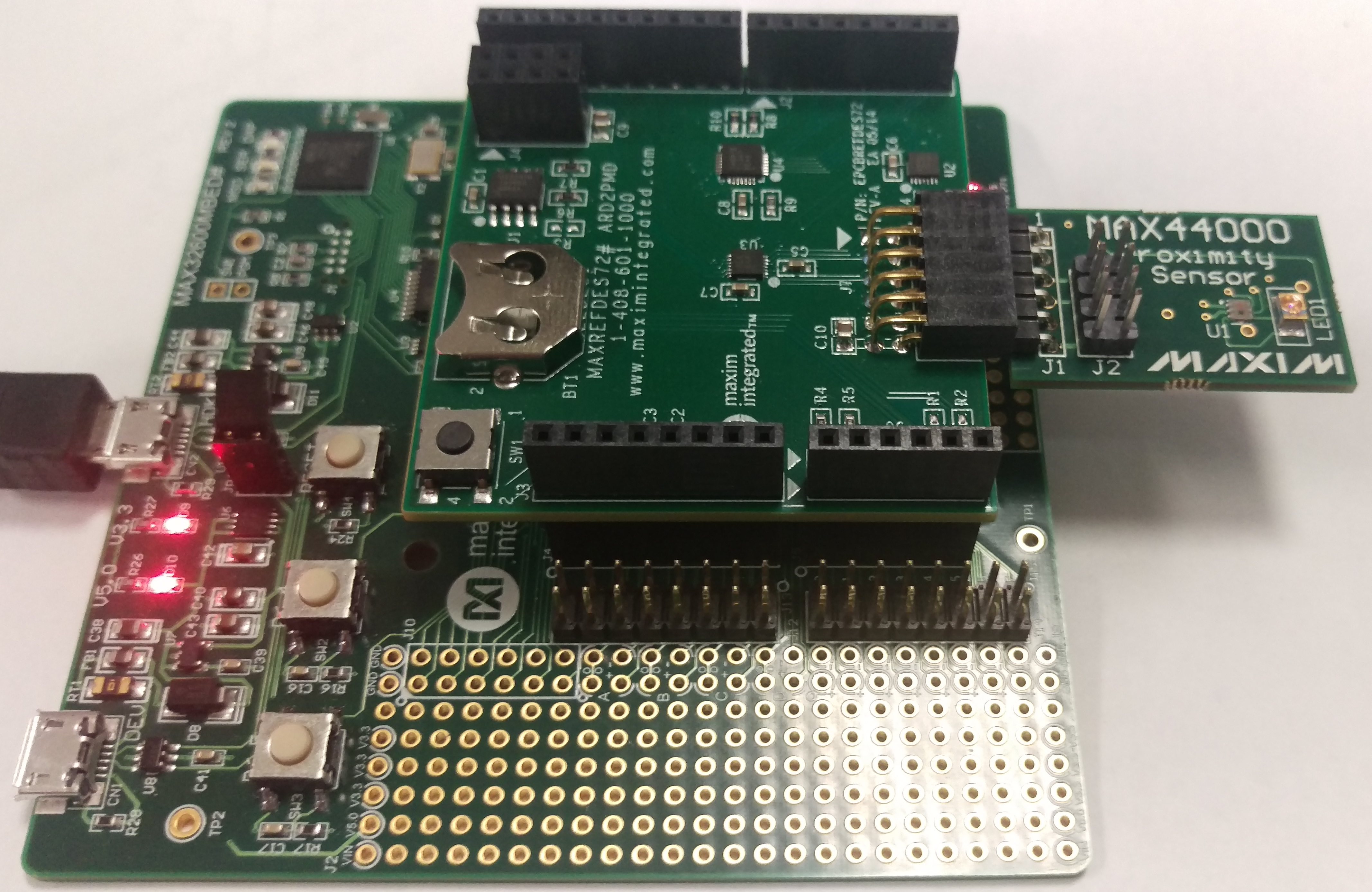
Demonstrates the MAX44000 library and some of the features of the MAX44000
Dependencies: MAX44000 ard2pmod mbed
Fork of ALS_ARD2PMOD_Demo by
MAX44000PMB1 Demonstration
This demonstrates some of the capabilities of the MAX44000. This is written to work with the MAXREFDES72# adapter board and the MAX44000PMB1 peripheral module. It uses the standard Arduino pin names and it will compile for most arduino form-factor mbed boards.
 To run this demonstration you will need:
- MAX44000PMB1 Ambient Light / Proximity Sensor Peripheral Module
- MAXREFDES72# Pmod Adapter for Arduino Platforms
- An mbed enabled board with an Arduino compatible socket. We recommend the MAX32600MBED
In this demonstration the LEDs are changed based on data from the sensor.
- LED1 toggles when something is first detected by the proximity sensor.
- LED2 indicates when the Ambient Light Sensor reads greater than a set value (alsLim).
- LED3 will stay on whenever something is detected by the proximity sensor and stay on for an additional 5s after it is no longer detected.
Note: Some boards use D13 for an LED signal, so this example uses the second row (row B, pins 7 through 12) of the Pmod connector.

Tested platform boards
Links to external supporting material
- MAX44000PMB1 Ambient Light / Proximity Sensor Peripheral Module
- MAXREFDES72# Pmod Adapter for Arduino Platforms
- MAX32600MBED
main.cpp
- Committer:
- switches
- Date:
- 2016-04-08
- Revision:
- 8:fb192510004d
- Parent:
- 7:0a59d9e914f3
- Child:
- 9:22f6995ab785
File content as of revision 8:fb192510004d:
/* MAX44000 Ambient Light Sensor / Proximity Sensor Demo
 * This demonstrates some of the capabilities of the MAX44000.
 *
 * This is written to work with the ARD2PMD adapter board and
 * the MAX44000PMB1.  It uses the standard Arduino pin names
 * and it will compile for most arduino form-factor mbed boards.
 *
 * LED1 toggles when something is first detected by the proximity sensor.
 * LED2 indicates when the Ambient Light Sensor reads grater than alsLim.
 * LED3 will stay on whenever something is detected by the proximity sensor
 *   and stay on for an additional 5s after it is no longer detected.
 *
 * The following boards have been tested to work:
 *   MAX32600MBED
 *   FRDM-KL25Z
 *   FRDM-K64F
 *   Seeeduino Arch (LEDs inverted)
 *   Seeeduino Arch Pro
 *   ST Nucleo L152RE/F401RE (B row only, single LED, inverted)
 *   LPCXpresso1549
 *
 * Some boards use D13 for an LED signal, so this example uses the second
 *   row (row B, pins 7 through 12) of the Pmod connector.
 */

#include "mbed.h"
#include "ard2pmod.h"

I2C i2c(D14, D15);
DigitalOut tog(LED1);
DigitalOut als(LED2);
DigitalOut dly(LED3);
DigitalIn pb3(D6);  // Set as input to remove load from PB3
DigitalIn pb4(D7);  // Set as input to remove load from PB4
DigitalIn pa3(D12);  // Set as input to remove load from PA3
DigitalIn pa4(D13);  // Set as input to remove load from PA4

const int alsAddr = 0x94;
const int alsLim = 0x0008;

int main()
{
    Ard2Pmod ard2pmod(Ard2Pmod::PMOD_TYPE_I2C_B);  // Configure ard2pmod multiplexer for I2C
    char cmd[2];
    int alsData;

    cmd[0] = 0x02;  // Receive Register
    cmd[1] = 0xFC;  // 1.56ms, 1x
    i2c.write(alsAddr, cmd, 2);

    cmd[0] = 0x03;  // Transmit Register
    cmd[1] = 0x0F;  // 110mA
    i2c.write(alsAddr, cmd, 2);

    cmd[0] = 0x01;  // Config Register
    cmd[1] = 0x10;  // ALS/Prox Mode
    i2c.write(alsAddr, cmd, 2);

    bool lastProx = false;
    int offDelay = 0;
    tog = false;
    als = false;
    dly = false;

    while (true) {
        wait (0.02);
        cmd[0] = 0x05; // ALS Data Register Low
        i2c.write(alsAddr, cmd, 1, true);
        i2c.read(alsAddr, cmd, 1);
        alsData = cmd[0];
        als = (alsData < alsLim);

        cmd[0] = 0x16; // Prox Data Register
        i2c.write(alsAddr, cmd, 1, true);
        i2c.read(alsAddr, cmd, 1);
        if (cmd[0]) {
            if (!lastProx) {
                tog = !tog;
            }
            lastProx = true;
            offDelay = 250;
            dly = false;
        } else {
            lastProx = false;
        }
        if (offDelay > 0) { offDelay -= 1; }
        else { dly = true; }
    }
}

 Ambient Light and Proximity Sensor MAX44000