This program is guided to help establish a connection between two RFM95 900MHz LoRa radio modules using Maxim Integrated's Feather MCUs (MAX32630FTHR Mbed and the MAX32620FTHR Mbed). Once the radios are configured after powering on and if the radios are wired correctly, the two radios will self identify as either a master or a slave, and will then proceed to PING and PONG back and forth. Information about what is happening between the radios can be seen if the two boards are hooked up to a USB COM port through the included DAPLINK modules.
Dependencies: BMI160 BufferedSerial SX1276GenericLib USBDeviceHT max32630fthr
Fork of MAX326xxFTHR_LoRa_RFM95 by
RFM95 LoRa Example Ping Pong Program
Getting Started
This program has the support for sx1276 (Adafruit RFM95W LoRa Radio Transceiver Breakout - 900 MHz) and (Adafruit LoRa Radio FeatherWing - RFM95W 900 MHz) to work with a few different mbed boards (see PinMap.h for supported boards). However, this specific program is set up to work with the following mbed boards and RFM95 915MHz LoRa radios and the given pin diagrams without modifications: MAX32620FTHR and MAX32630FTHR.
Configuring the LoRa Radio
The setup for the radio can be found in <<SX1276GenericPingPong/GenericPingPong.cpp>>, which can be found by navigating from the root directory. Setup for the radio starts on line #14 in <<SX1276GenericPingPong/GenericPingPong.cpp>>.
Choosing the Correct Frequency
This program was written with libraries compatible with RFM95 LoRa 900MHz Radio modules. The radio's frequency is able to be tuned dynamically, however this program configures the frequency by programming registers at device power on. The 900MHz module supports both 868MHz and 915MHz operation. Check local laws for which band around 900MHz is set aside for the scientific, commercial, and/or license free usage in your country. The supported frequencies can be found in <<SX1276GenericLib.lib/sx1276/sx1276.h>>
They are also listed below for convenience:
SX1276GenericLib.lib/sx1276/sx1276.h
typedef enum {
    RF_FREQUENCY_868_0 = 868000000, //Hz
    RF_FREQUENCY_868_1 = 868100000, //Hz
    RF_FREQUENCY_868_3 = 868300000, //Hz
    RF_FREQUENCY_868_5 = 868500000, //Hz
    RF_FREQUENCY_915_0 = 915000000, //Hz
    RF_FREQUENCY_915_1 = 915100000, //Hz
    RF_FREQUENCY_915_3 = 915300000, //Hz
    RF_FREQUENCY_915_5 = 915500000, //Hz
} rf_frequency_t;
Please chose a supported frequency above that is compatible with your RFM95 (or likewise single band compatible sx1276 radio) module and change line #22 in <<SX1276GenericPingPong/GenericPingPong.cpp>> to the correct enum above.
Wiring
This program is aimed at working without modifications with RFM95W LoRa 900MHz modules in both a Breakout board and a FeatherWing version.
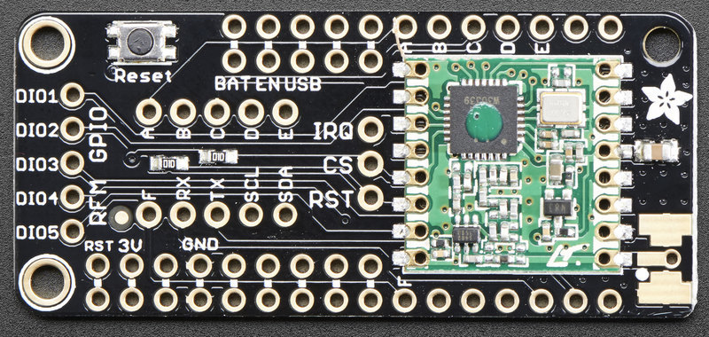
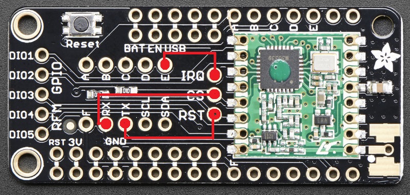
FeatherWing setup
This wiring diagram is useful if your RFM95W LoRa 900MHz module is a Feather wing made by Adafruit.
Before jumpers are soldered in:

After jumpers are soldered in:

Note: The default pin configurations for the radio in this program (found in <<PinMap.h>> under targets MAX32630FTHR and MAX32630FTHR ) can be changed to suite additional modifications built from a fork of this program repo. If this is the case, the diagrams above will need to be changed to suite the new pin map.
For more information, a detailed wiring guide for the RFM95W Featherwing can be found here.
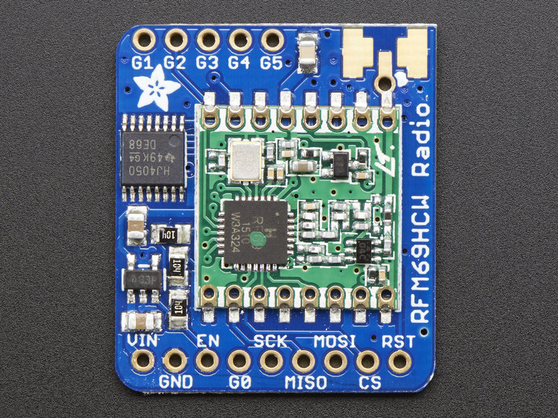
Breakout Board
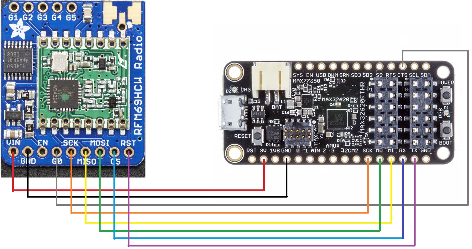
For a breakout board, the following wiring diagram will work with both the MAX32630FTHR and the MAX32630FTHR mbed boards if wired in the same locations:
Before the RFM95W is connected with wires:

After the RFM95W is connected with wires:

The representations of the connections above can be found in<<PinName.h>> under targets MAX32630FTHR and MAX32630FTHR.
This default pin configuration will set you up with a connection to the MCU.
For more information, a detailed wiring guide for the RFM95W Brakout Board can be found here.
Antenna
Since this is radio communication, we are going to need antennas to be attached to both of the Radios used in this example.
For more information on how to solder an antenna to the RFM95, please click here
