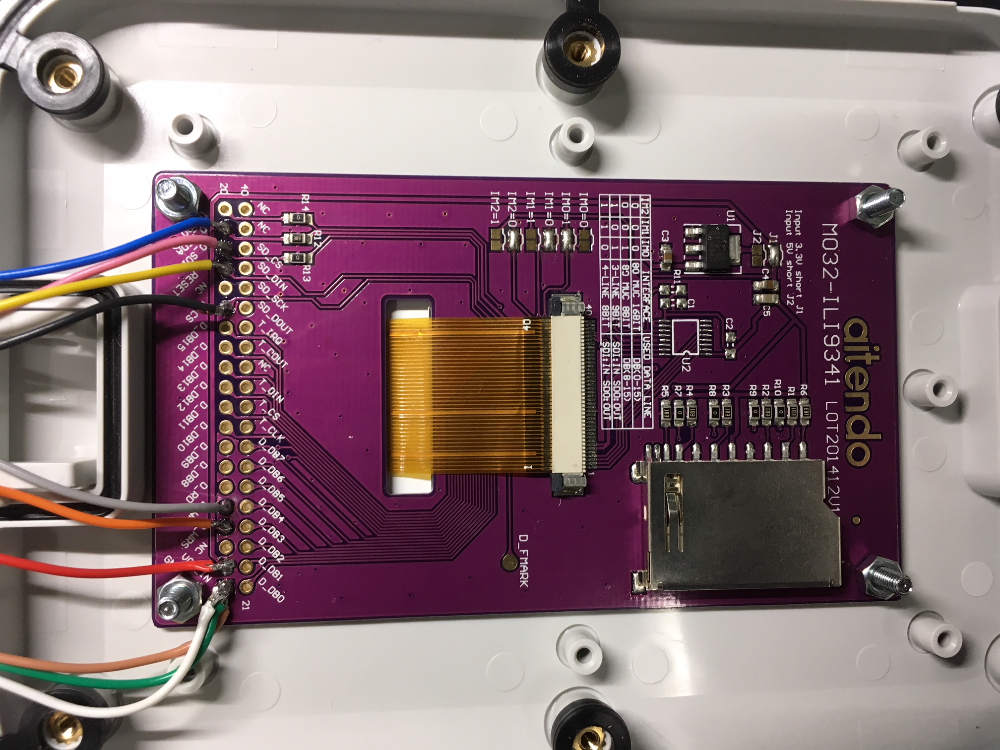
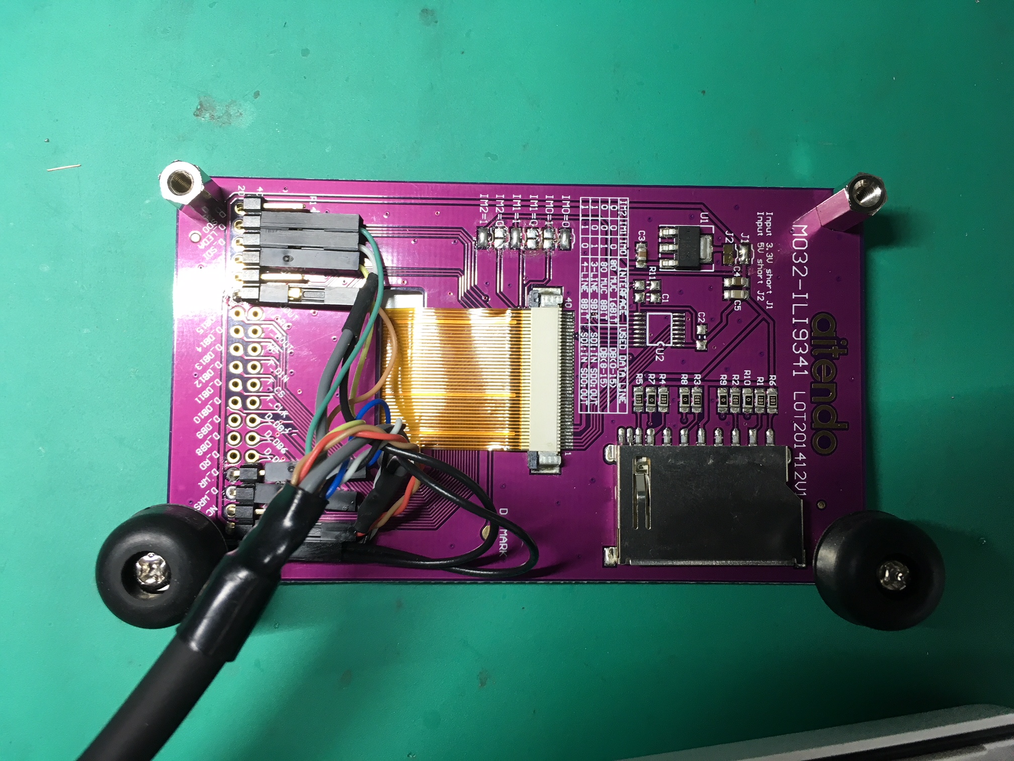
Temporary Connector Reversed Version
Dependencies: UniGraphic mbed vt100
afero_poc15_180403R , J1 のピン配置を反転させたヴァージョンです。
Color2系を使用するためには以下のピンをジャンパで接続してください。
J1-D7 <-> J1-D0
J1-D6 <-> J1-D1
(調査中) また、こちらでテストした範囲では、
FRDM-KL25Z の V3.3 を、Modulo2 の VCC_3V3 ピンに接続してやる必要がありました。
尚、J1-D1, D0 を使用するために UART を無効にしているため
ログは表示されません。
TFTモジュールについて
aitendoのTFTモジュールはデフォルトでは8bit bus モードになっています。

半田のジャンパを変えて、SPIの設定にしてください。

サーミスタについて
POC1.5 では サーミスタは 25℃の時に抵抗値が 50.0kΩになる502AT-11 が
4.95kΩのプルアップ(実際は10kΩx2の並列)で使用されていました。
今回の試作では抵抗値が 10.0kΩの 103AT-11 が
5.1kΩのプルアップで使用されていますので、係数を合わせるために
SMTC502AT-11 のコンストラクタを
R0 = 10.0
R1 = 5.1
B = 3435
T0 = 298.15
で呼ぶように変更しました。
edge_utils/edge_reset_mgr.cpp
- Committer:
- Rhyme
- Date:
- 2018-04-24
- Revision:
- 0:0b6732b53bf4
File content as of revision 0:0b6732b53bf4:
#include "mbed.h"
#include "edge_reset_mgr.h"

/**
  * System Reset Status Register 0 (RCM_SRS0) 0x4007_F000
  *
  * bit[7] : POR         Power-On Reset
  * bit[6] : PIN         External Reset Pin
  * bit[5] : WDOG        Watchdog
  * bit[4] : (Reserved)
  * bit[3] : LOL         Loss-of-Lock Reset
  * bit[2] : LOC         Loss-of-Clock Reset
  * bit[1] : LVD         Low-Voltage Detect Reset
  * bit[0] : WAKEUP      Low Leakage Wakeup Reset
  */
#define REG_RCM_SRS0    (uint8_t *)0x4007F000
#define POR_RESET_BIT   0x80
#define PIN_RESET_BIT   0x40
#define WDG_RESET_BIT   0x20
#define LOL_RESET_BIT   0x08
#define LOC_RESET_BIT   0x04
#define LVD_RESET_BIT   0x02
#define WUP_RESET_BIT   0x01

  /**
   * System Reset Status Register 1 (RCM_SRS1) 0x4007_F001
   *
   * bit[7:6] (Reserved)
   * bit[5] : SACKERR     Stop Mode Acknowledge Error Reset
   * bit[4] : (Reserved)
   * bit[3] : MDM_AP      MDM-AP System Reset Request
   * bit[2] : SW          Software Reset
   * bit[1] : LOCKUP      Core Lockup
   * bit[0] : (Reserved)
   */
#define REG_RCM_SRS1     (uint8_t *)0x4007F001
#define SACK_RESET_BIT   0x20
#define MDM_RESET_BIT    0x08
#define SW_RESET_BIT     0x04
#define LOCKUP_RESET_BIT 0x02

#define IDX_POR_RESET    0
#define IDX_PIN_RESET    1
#define IDX_WDG_RESET    2
#define IDX_LOL_RESET    3
#define IDX_LOC_RESET    4
#define IDX_LVD_RESET    5
#define IDX_WUP_RESET    6
#define IDX_SACK_RESET   7
#define IDX_MDM_RESET    8
#define IDX_SW_RESET     9
#define IDX_LOCKUP_RESET 10

const char *reset_reason[] = {
    "Power On Reset",
    "Reset Pin Asserted",
    "Watch Dog Reset",
    "Loss of Lock Reset",
    "Loss of Clock Reset",
    "Low Voltage Detect Reset",
    "Low Leakage Wakeup Reset",
    "Stop Mode Acknowledge Error Reset",
    "MDM-AP System Reset Request",
    "Software Reset",
    "Core Lockup Reset",
    0
} ;

void print_reset_reason(void)
{
    extern char *reset_reason_str ;
    int idx = 0 ;
    uint8_t *data = REG_RCM_SRS0 ;
    if (*data & POR_RESET_BIT) {
        idx = IDX_POR_RESET ;
    }
    if (*data & PIN_RESET_BIT) {
        idx = IDX_PIN_RESET ;
    }
    if (*data & WDG_RESET_BIT) {
        idx = IDX_WDG_RESET ;
    }
    if (*data & LOL_RESET_BIT) {
        idx = IDX_LOL_RESET ;
    }
    if (*data & LVD_RESET_BIT) {
        idx = IDX_LVD_RESET ;
    }
    if (*data & LOC_RESET_BIT) {
        idx = IDX_LOC_RESET ;
    }
    if (*data & WUP_RESET_BIT) {
        idx = IDX_WUP_RESET ;
    }
    data = REG_RCM_SRS1 ;
    if (*data & SACK_RESET_BIT) {
        idx = IDX_SACK_RESET ;
    }
    if (*data & MDM_RESET_BIT) {
        idx = IDX_MDM_RESET ;
    }
    if (*data & SW_RESET_BIT) {
        idx = IDX_SW_RESET ;
    }
    if (*data & LOCKUP_RESET_BIT) {
        idx = IDX_LOCKUP_RESET ;
    }
    printf("%s\n", reset_reason[idx]) ;
    reset_reason_str = (char *)reset_reason[idx] ;
}

/**
 * Software Reset
 *
 * From Cortex-M0 Devices Generic User Guide
 * 4.3.4 Application Interrupt and Reset Control Register
 *
 * Bit[31:16] : VECTCKEY
 * Bit[15]    : ENDIANESS
 * Bit[14:3]  : (Reserved)
 * Bit[2]     : SYSRESETREQ
 * Bit[1]     : VECTCLRACTIVE (reserved for debug use)
 * Bit[0]     : (Reserved)
 *
 * Note: To trigger software reset, both VECTKEY=0x05FA and SYSRESETREQ
 * must be written at once, therefore the value will be
 * 0x05FA0004
 */

void software_reset(void)
{
     SCB->AIRCR = 0x05FA0004 ;
}

/**
 * reset_watch_dog
 * reset the watch dog counter
 * this function must be called within the limit (1sec)
 */

void reset_watch_dog(void)
{
    SIM->SRVCOP = (uint32_t)0x55u;
    SIM->SRVCOP = (uint32_t)0xAAu;
}
 La Suno