Pinout and Logic Flow
Pinout
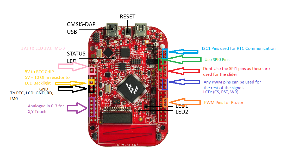
The pinout of the KL46Z can be shown as below leading to the various components

Logic Flow
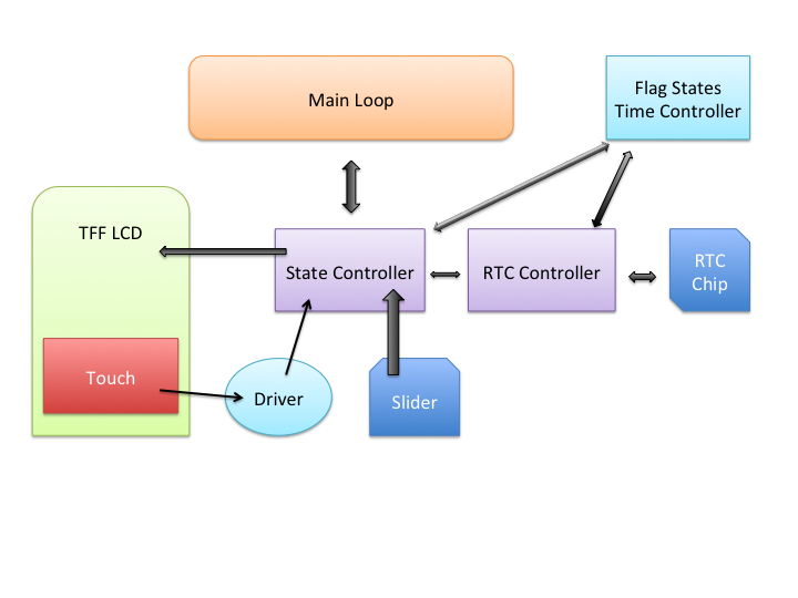
Due to the unavailability of interrupts from lack of independent touchscreen driver, a linear programming approach was used. This meant the implementation of the touchscreen driver within the code itself, as a result, the code had to be adjusted accordingly.
Main.cpp
Initialises the constants takes care of state switching using global flag : f_state
States
Each state controller has its own built-in touch logic to decide the responses to touch. To change states, each controller will change the global f_state flag in order to return to the main loop for the state handler to kick in.
RTC
A library is used to interact with the RTC. The RTC chip takes care of time incrementation and time keeping, if more time had been permitted, and implementation to use extra available memory space on the RTC chip would have been used to store the Alarm setting.
Touchscreen
The polling driver will return the X and Y co-ordinates in addition to the whether it was being touched.
Alarm
The alarm was handled inside the State controller in order to preserve integration capability in the code due to lack of external touchscreen driver.
Slider
The slider gives a percentage reading, by storing its global states of the last reading, it is able to work out a difference and as a result allows the addition of relative adjustment.
Whiteboard
The whiteboard function is an example code included with the forked library used to test the touchscreen. This has been included for added functionality
Flow Chart
