You are viewing an older revision! See the latest version
Gesture Controlled Robot Project
Team
Jordan Hughes
Stephen Piper
Alex Simoneaux
Kevin Whitmore
Overview
The purpose of our project is to construct a robot that can be controlled by hand movements with several other add-ons, like numerous LED's and a speaker which plays a song.
Components Needed
- Zigbee (XBee Series 2) (2)
- Emgreat Robot Chassis (Includes 2 DC motors, chassis, and battery pack)

Wiring Diagrams
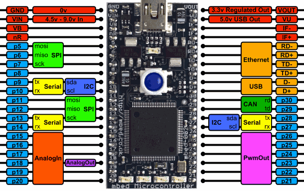
For each Mbed, a visual overview is included first to give an easy overview of how the entire Mbed is pinned out the various components. Following this general overview are the various pin outs for specific components, as well as any general reminders for that specific part (ex: attaching a resistor in series with an LED).
Mbed 1 Hardware & Wiring
Mbed1 is solely responsible for interpreting the users hand gestures and transmitting the appropriate command to Mbed2 using one of the Zigbees.
Visual Overview
The visual overview is provided below, and is a nice way to quickly reference the various hookups to Mbed1 to ensure that the general wiring is correct.
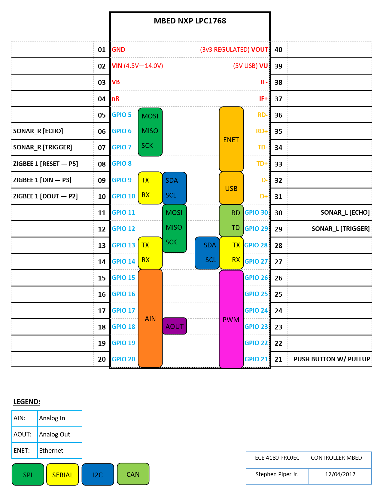
Zigbee1 Connection
The following is a table which states how to wire Zigbee1 to MBed1
| Mbed 1 | Zigbee 1 |
|---|---|
| Pin 8 | Reset - Pin 5 |
| Pin 9 | DIn - P3 |
| Pin 10 | DOut - P2 |
Ultrasonic Connections
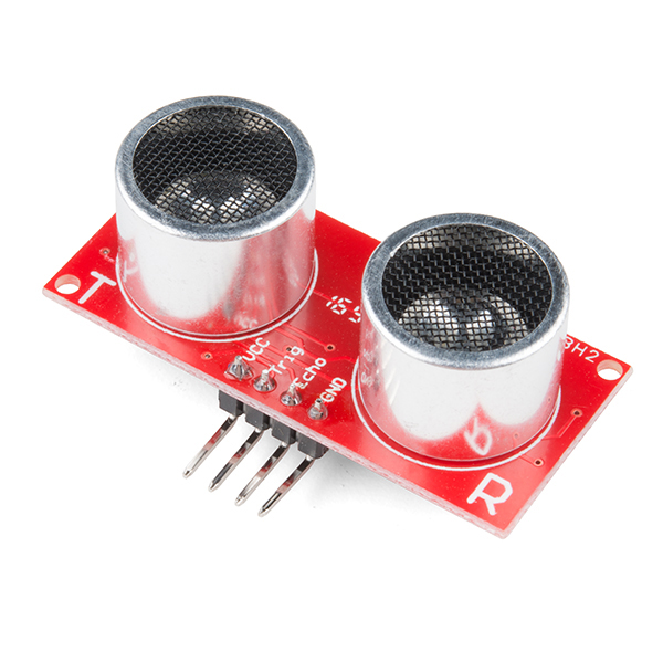
This table shows how to connect both sonar devices to MBed1.
| Mbed 1 | Ultrasonic Right | Ultrasonic Left |
|---|---|---|
| Pin 6 | Echo | No Connect |
| Pin 7 | Trigger | No Connect |
| Pin 30 | No Connect | Echo |
| Pin 29 | No Connect | Trigger |
Mbed 2 Hardware & Wiring
MBed2 is responsible for receiving commands sent from MBed1 and controlling the lighting and DC motors.
Visual Overview
An overview of the pin out for MBed2 is seen below. This focuses on the numerous connections between the MBed2 and various devices.
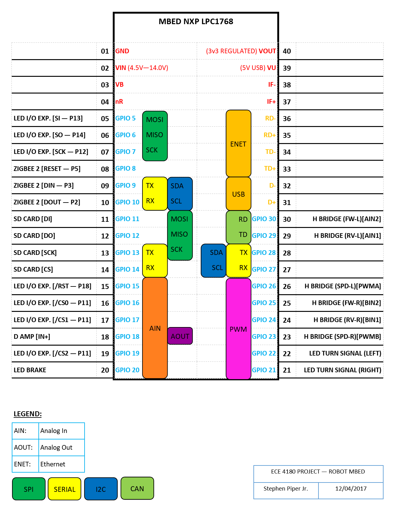
Voltage Regulator
The voltage regulator schematic is included below:

Zigbee Connections
| Mbed 2 | Zigbee 2 |
|---|---|
| Pin 8 | Reset - Pin 5 |
| Pin 9 | DIn - P3 |
| Pin 10 | DOut - P2 |
Class-D Amplifier
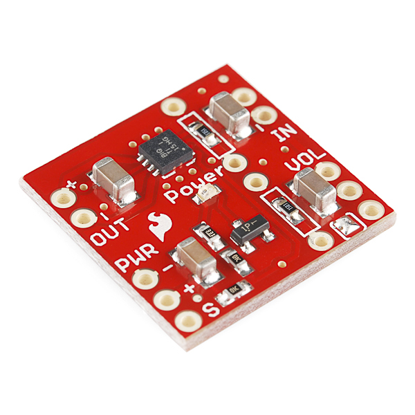
Here is a pin out for the Class-D Amplifier which shows its connections to the speaker and MBed 2.
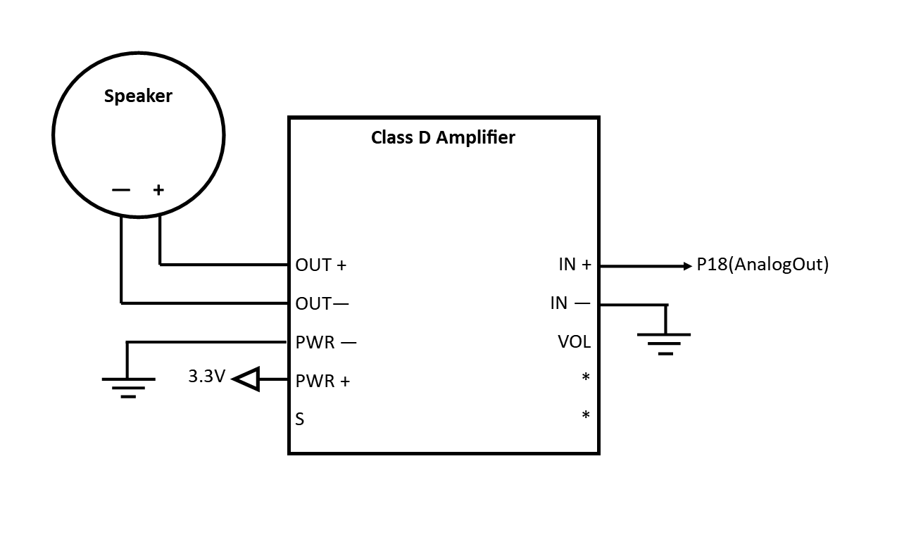 Connections not drawn are simply not connected.
H Bridge Connections
The following is a pin out demonstrating how to connect the H-Bridge to the two DC motors.
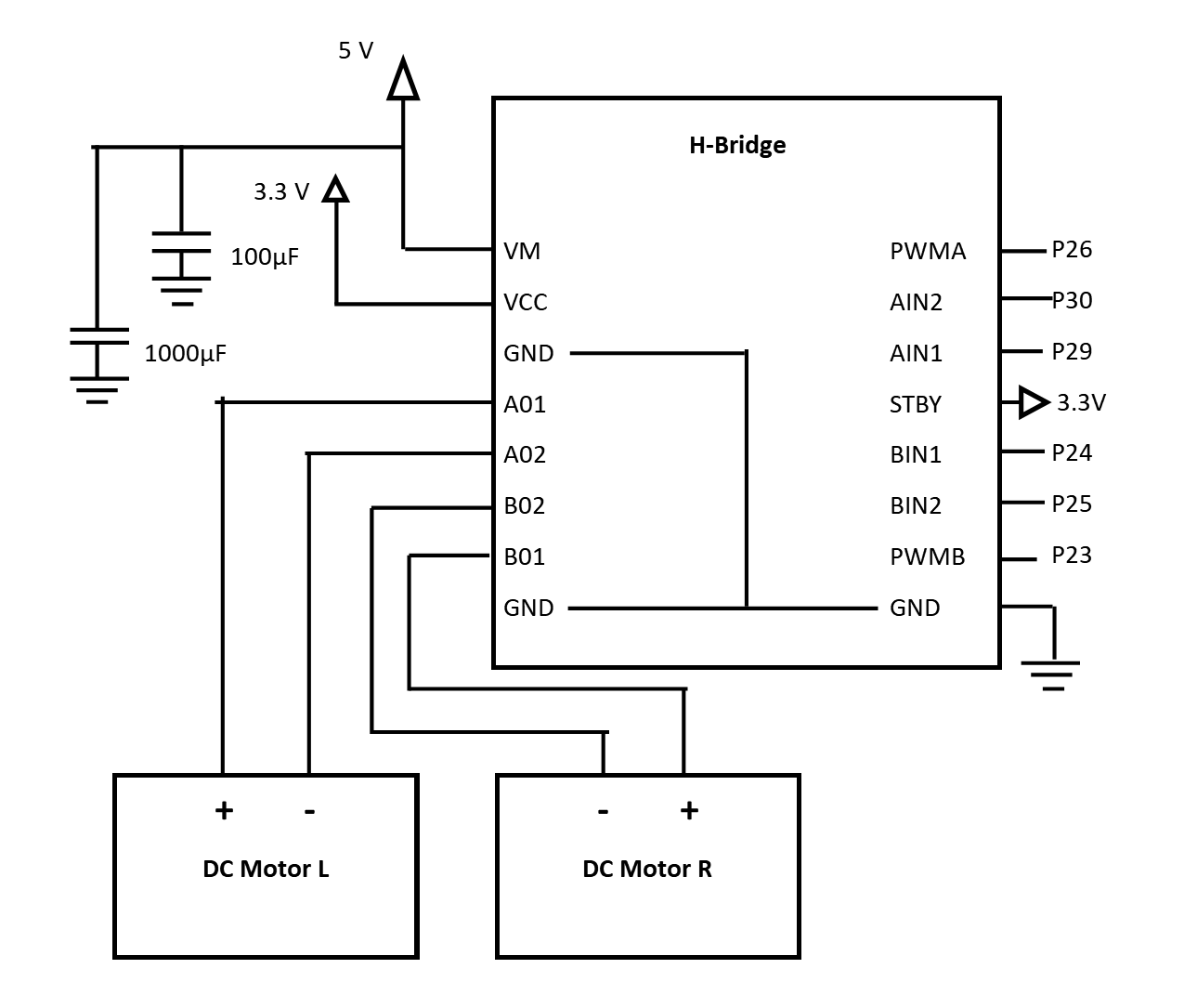 Note that in this picture, all of the ground connectors on the H-bridge are connected to ground. The following is a table which focuses on the connections between the Mbed2 and the H-bridge.
| Mbed 2 | H Bridge |
|---|---|
| Pin 30 | RV-L - AIN2 |
| Pin 29 | FW-L - AIN1 |
| Pin 26 | SPD-L - PWMA |
| Pin 25 | RV-L - BIN2 |
| Pin 24 | FW-L - BIN1 |
| Pin 23 | SPD-R - PWMB |
SD Card Reader
Here is a pin out diagram of the SD Card Reader.
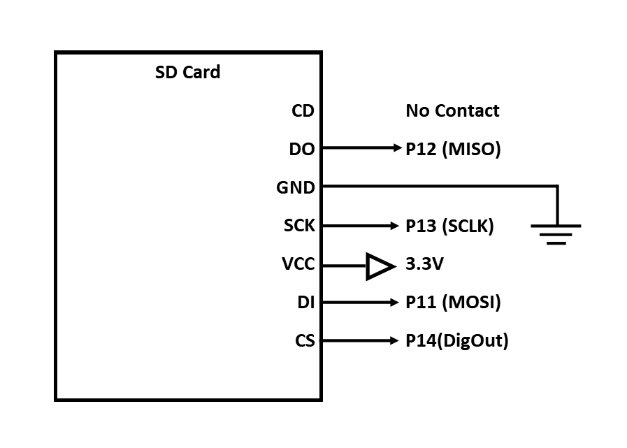 Note that you will need to save the file you wish to play onto the SD Card and alter the code for MBed2 to play your chosen wav file. This line of code is found in main.cpp for the MBed2 code.
main.cpp
void speaker()
{
    //Mount the filesystem
    //sd.mount();
    //wave_file=fopen("/sd/wavfiles/police_siren.wav","r");
    //waver.play(wave_file);
    //Thread::wait(31000);  //wait 31 seconds
    while(1)
    {
        if (RX_char == 'w')
        {
            wave_file=fopen("/sd/wavfiles/police_siren.wav","r");
            waver.play(wave_file);
            fclose(wave_file);
            Thread::wait(31000);  //wait 31 seconds
        }
        Thread::wait(500);  //wait 500ms
    }
}
Specifically, the police_siren.wav should be changed to nameofyourwavfilehere.wav
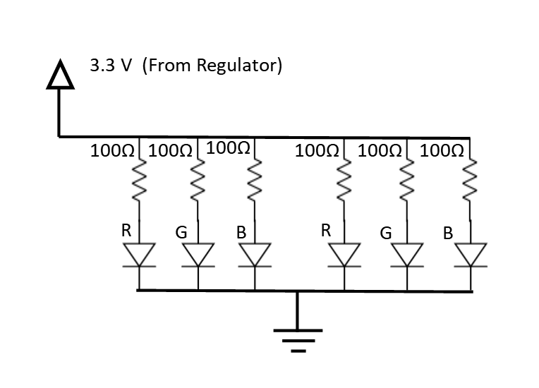
HeadLamp LED Connections
The headlamps for the robot car are not connected to MBed2, but are hardwired to accept voltage from the regulator. In other words, when the robot car is on, the headlamp LEDs are on. Here is a schematic which shows how the headlamps should be wired.
Turn Signals & Brake Lights
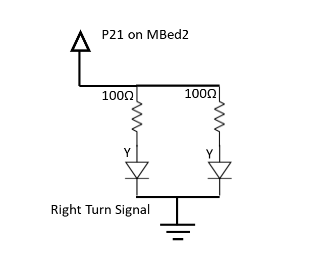
The four yellow LEDs should be connected to output pins P22 and P21 on the MBed2 to enable the turn signals on the car.A schematic for the left turn signal is shown below :
And the right turn signal is similar:
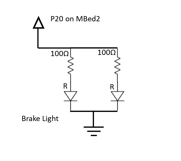
The brake lights are the same, but are hooked to P20 on Mbed2 and use the red LEDs as shown:
For quick reference, here is a table showing just the connections between the LED networks and the Mbed2 pins:
| MBed 2 | LED network |
|---|---|
| Pin 20 | Brake LEDs |
| Pin 21 | Right Turn LEDs |
| Pin 22 | Left Turn LEDs |
MCP23S17
The MCP23S17s are responsible for controlling all of the RGB LEDs, allowing the car to have more than would be possible with just the MBed.
Note that each MCP is responsible for one of the RGB LED values (one MCP for red, one for green, etc). The schematic for how the Red and Green LED control MCP's is connect to the series of led is shown below: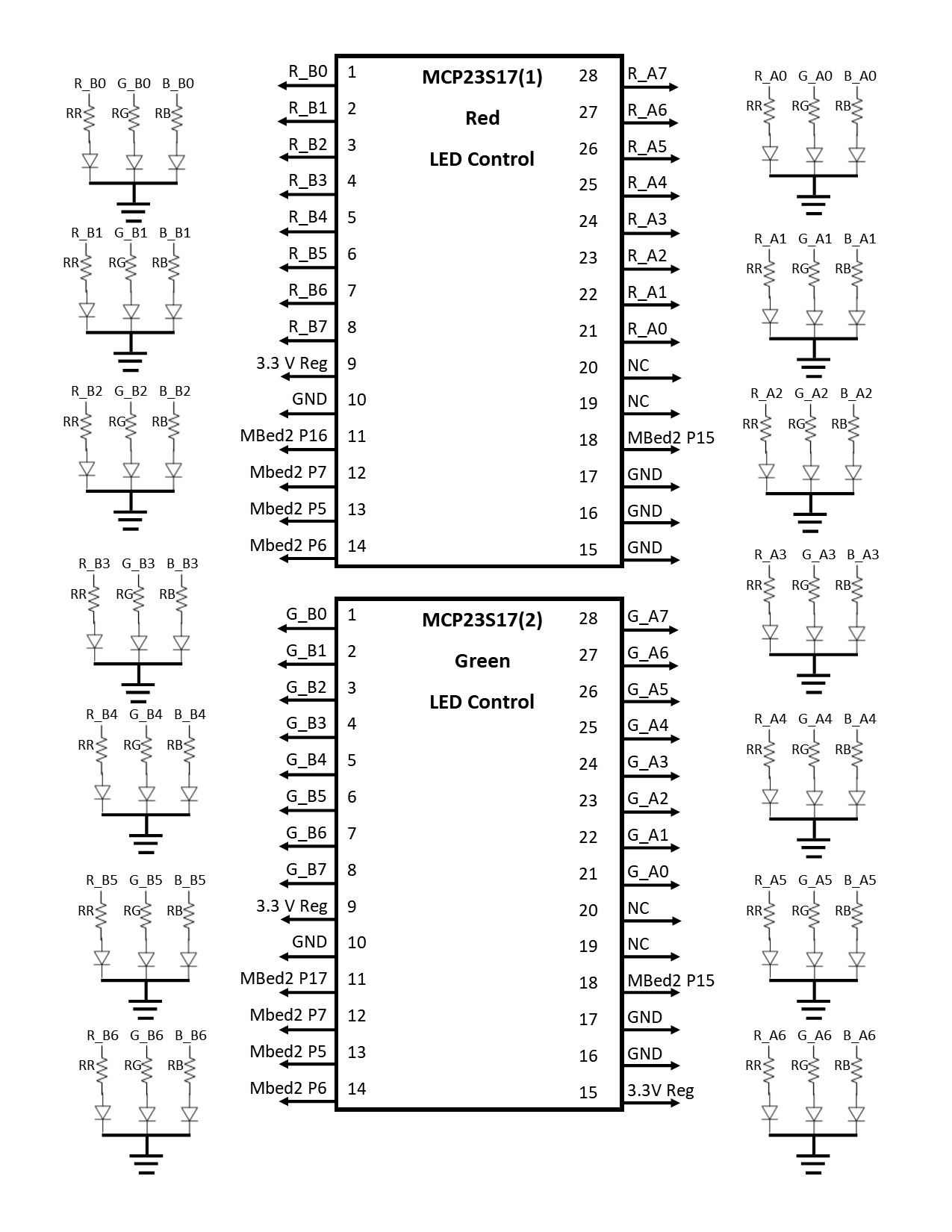
And the Blue LED control MCP, as well as the resistor values, is included in the next image:
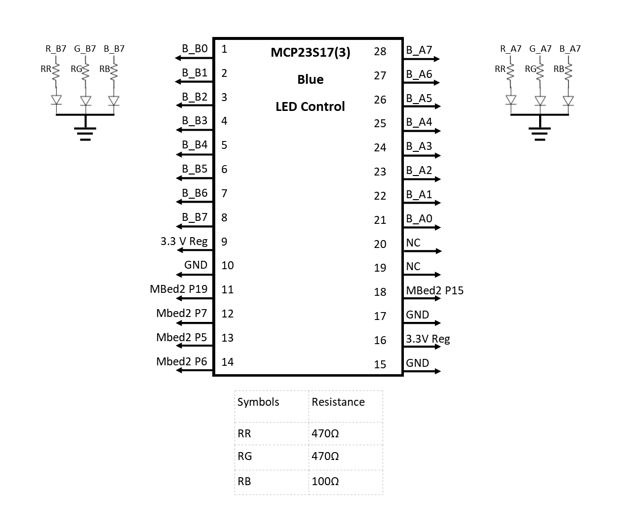
Also, for quick checking the connections between each MCP and Mbed2 can be seen below
| Mbed 2 | MCP23S17 (all) |
|---|---|
| Pin 5 | SI- Pin 13 |
| Pin 6 | SO- Pin 14 |
| Pin 7 | SCK - Pin 12 |
| Vout | VDD - Pin 9 |
| Gnd | VSS - Pin 10 |
| Pin 15 | Reset - Pin 18 |
| Mbed 2 | MCP23S17 (1) |
|---|---|
| Pin 16 | Pin 11 |
| Mbed 2 | MCP23S17 (2) |
|---|---|
| Pin 17 | Pin 11 |
| Mbed 2 | MCP23S17 (3) |
|---|---|
| Pin 19 | Pin 11 |
Software Components
Mbed 1
Import programMBed1
Needed program to run the mbed responsible for interpreting hand gestures and transmitting them to the second mbed
Mbed 2
Import programECE4180_PROJECT_ROBOT
Initial Release
Additional Information
Mbed
For more information about the mbed LPC1768, check out the product page and datasheet
Ultrasonic Senors
For more information about the ultrasonic sensors, check out the mbed page or examine the datasheet.
Speaker
For additional readings, see the mbed speaker wiki page, or view the datasheet
LEDs
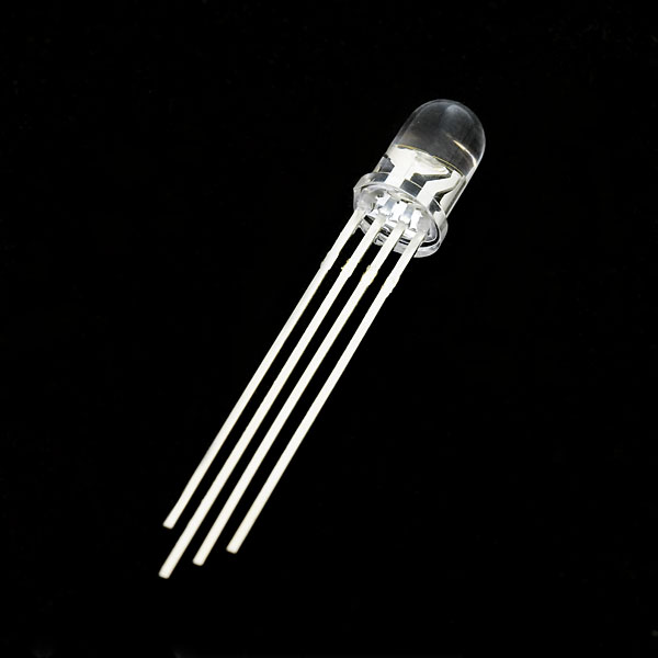
Additional information on the red LED's can be found in its datasheet. More information about the RGB LED's can be found on the mbed wiki page or in the datasheet.
