Important changes to repositories hosted on mbed.com
Mbed hosted mercurial repositories are deprecated and are due to be permanently deleted in July 2026.
To keep a copy of this software download the repository Zip archive or clone locally using Mercurial.
It is also possible to export all your personal repositories from the account settings page.
Dependencies: mbed 4DGL-uLCD-SE mbed-rtos nRF24L01P
Homepage
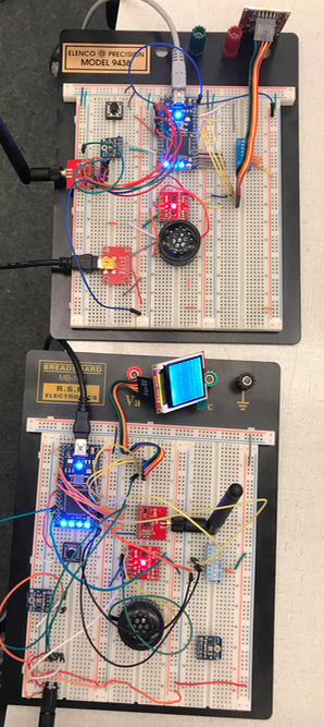
Mbed Walkie Talkie
Created by: Jack Sacane, Joseph Neiger, David Rechtmann
Description
This project allows two people to communicate with each other using mbed devices connected to microphones and speakers. These two portable devices will produce audio of recognizable quality from a distance of up to 100 meters.
Functionality
By pressing down a pushbutton and speaking into a microphone, the mbed will use the attached transceiver to send packets of data over RF to the other mbed's transceiver to be played on a speaker. By not pressing down the pushbutton, an mbed will be able to receive data from other Walkie Talkie mbeds, as long as they are on the same channel as it. The device is capable of transmitting over 6 channels for privacy or interference avoidance.
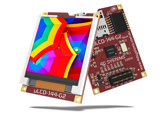
A uLCD screen shall display the status of the device, in terms of whether it is transmitting or receiving as well as which channel the device is at.
Hardware
Parts
- 2x NRF24L01 Transceiver (https://www.sparkfun.com/products/705)
- 2x 2.4 GHz Duck Antenna RP-SMA (https://www.sparkfun.com/products/145)
- 2x uLCD-144-G2 (https://www.sparkfun.com/products/11377)
- 2x Adafruit MEMS Microphone (https://www.adafruit.com/product/2716)
- 2x PCB Mount Speaker (https://www.sparkfun.com/products/11089)
- 2x TPA2005D1 Class D High Efficiency Audio Amplifier (https://www.sparkfun.com/products/11044)
- 2x Pushbutton
- 2x DIP switch
- 2x 5V power supply
Pin Outs
(in progress)

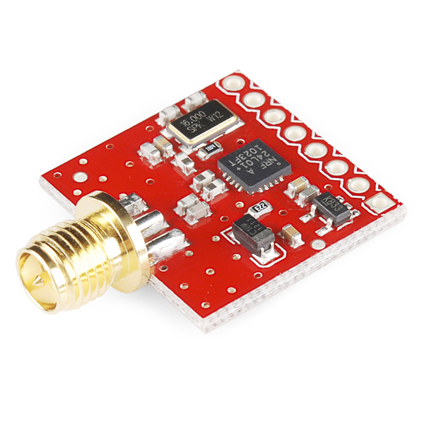
| mbed | Transceiver |
|---|---|
| p5 | mosi |
| p6 | miso |
| p7 | SCK |
| p8 | CSN |
| p9 | CE |
| p10 | IRQ |
| Gnd | Gnd |
| 5V | Vcc |
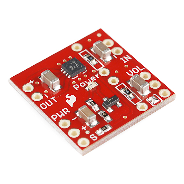
| mbed | Class D Audio Amp | Speaker |
|---|---|---|
| Gnd | in- , pwr - | |
| p18 (PWM) | in+ | |
| out+ | + | |
| out- | - | |
| 3.3V | pwr+ |
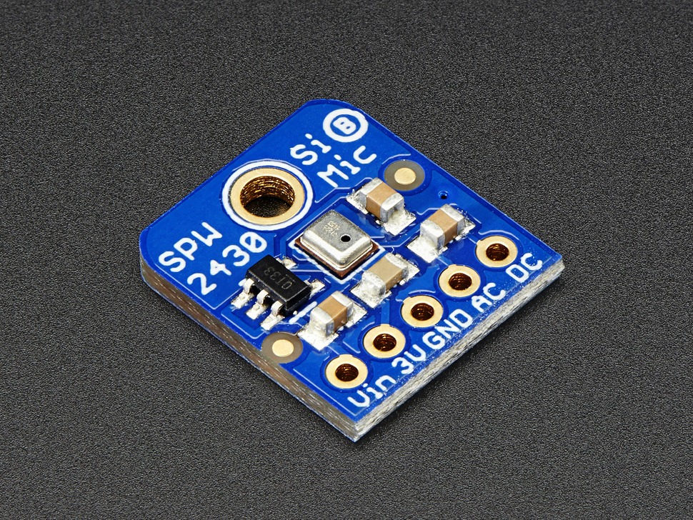
| mbed | MEMS Microphone | |
|---|---|---|
| p16 (AnalogIn) | DC | |
| Gnd | Gnd | Gnd |
| 5V | Vu |
| mbed | uLCD display |
|---|---|
| p28 | Tx |
| p27 | Rx |
| p29 | Reset |
| Gnd | Gnd |
| 5V | 5V |
| mbed | buttons |
|---|---|
| p12 | pushbutton |
| p21 | dip 1 |
| p22 | dip 2 |
| p23 | dip 3 |
| p24 | dip 4 |
| p25 | dip 5 |
Software
The program is split into 3 main parts: sampling the microphone, transmitting and receiving the data, and outputting the data to the speaker.
Sampling the Microphone
The microphone is an analog signal with a DC bias. This DC bias is not completely constant as it depends on the intensity of some of the previously sampled sound data. For example, a loud clap causes the DC bias to jump significantly and then slowly revert to the "base-line" DC value found in the data sheet. To account for this, a complementary filter is used to estimate the DC bias. This can realistically be done since the signal "averages" around the DC value over the long term. Once the microphone is sampled, we convert the sample from a float point value to an 8 bit unsigned integer. The reasons for this will be explained in the next section.
Once the microphone has been sampled, the next step is push the samples onto a queue for data transmission over RF. This is done using a "Circular Buffer". The "Circular Buffer" uses an array as the underlying data structure and keeps track of the start and end of the data within. Instead of the start of the array always signifying the beginning of the queue and constantly shifting the data down, there are underlying variables that keep track of the beginning and end of the queue and the array is "shifted". This is much cheaper computationally as all the data doesn't need to be continuously copied as things are pulled from the queue.
Transmitting and Receiving Data
Since there can be multiple devices trying to transmit at once, it is important to keep the airways as clean as possible. One way to do this is to compress the data and place it into packets to send. For the Walkie-Talkie, the float microphone values are converted to a scaled 8 bit unsigned integer. The LSB value for the scaled integers is 1/255. Thus, a 1 read on the microphone line is 255 when converted to the integer and a 0 on the microphone line is a 0 when converted to integer. This saves 3 bytes when transmitting without much loss in accuracy. Additionally, instead of sending only one sample at a time, 32 samples are packaged together into a packet and sent. This allows for a higher data to transmission ratio since there are always a few bytes of overhead.
When sending the data, 32 samples are taken from the "Circular Buffer" and place into the transmit queue on the RF chip. Once the other device receives the data, it pulls it off the receive buffer and places it into another "Circular Buffer" used to store the speaker values.
Outputting to the Speaker
In time with the microphone sampler, a single byte is removed from the speaker "Circular Buffer". This byte is scaled back to the float equivalent and is directly place onto the analog output pin controlling the speaker.
Class References
Import program
Public Member Functions |
|
| CircularBuf (unsigned int size) | |
|
Assigns a circular buffer of the given size.
|
|
| unsigned int | push (T *data, unsigned int size) |
|
Pushes data onto the buffer.
|
|
| unsigned int | pop (T *data, unsigned int size) |
|
Pops data from the buffer.
|
|
Block Diagram
