Important changes to forums and questions
All forums and questions are now archived. To start a new conversation or read the latest updates go to forums.mbed.com.
6 years, 12 months ago.
Getting error "Pinmap not found" for SPI using pins p5, p6, p7 in "Hello world" example on LPC1768
Context: I'm trying to connect an SDHC card to my LPC1768. After a long period of time trying different libraries, example codes etc with the card connected to pins 5-8, I connected my SD card to the SPI interface on pins 11-13 and found that it suddenly worked. Unfortunately I can't use those pins for the SD card because I need to use 2 UARTs and an I2C for my other peripherals, so I need to be able to use pins 5-8 for SPI.
Basic problem: I'm using the "Hello World" program found here: https://os.mbed.com/docs/mbed-os/v5.11/apis/spi.html When I use this with my card connected to pins p11, p12, p13, p14 it works fine - or at least it returns a "WHOAMI register = 0xFF" (I assume this is a reasonable thing for it to return). When I use it with card connected to pins p5,p6,p7,p8, it returns a "pinmap not found for peripheral".
What I've tried:
- Looking at the pins in the datasheet here: https://www.nxp.com/docs/en/data-sheet/LPC1769_68_67_66_65_64_63.pdf
I'm quite confused by this - looking at the pin numbers on pages 10-20 , they don't seem to match up with the numbers on the mbed
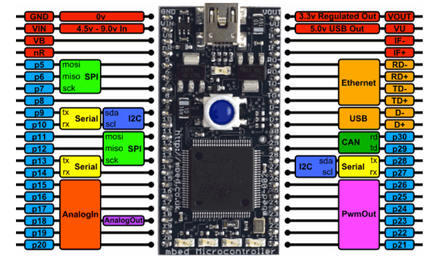
as far as I can tell there is an offset of 1, so p5 on the mbed (diagram below) would be p0[6] in the datasheet, I'm not sure how
consistent this is however, and by that logic the usual sequence of pins for SPI (mosi, miso, clock) are reversed, so it goes mosi, miso,
clock, cs for p0[9] down to p0[6] rather than 6 up to 9.

I am having some trouble understanding this and may not have explained the above very well, so if there is anyone who can explain how to interpret the pins in the datasheet with respect to the pins on the actual device I would be grateful
- A lot of searching on these forums and a bit of trying running code with different pin orders in the "SPI spi(args)" function. The error turns up immediately upon reset along with flashing lights on the mbed, and when I tried putting long flashes in the code they simply don't happen, so I guess the error message is generated before any code even runs. It is the same even when there is no device wired to the port. All this leads me to think that it's not my wiring that's causing the problem.
Thanks for reading this, any advice would be much appreciated.
2 Answers
6 years, 12 months ago.
Double check for typos or something else also using those pins, I've got code using that board which has the line SDFileSystem sdCard(p5,p6,p7,p8, "sd", NC, SDFileSystem::SWITCH_NONE, 10*1000*1000); and the SD card works fine so it should all be OK.
Alternatively can you change the pins you use for the UARTs?
The diagram doesn't show all the possible pin mappings since it would get too complicated or you'd get someone trying to use the same UART on two different sets of pins and getting very confused.
UART1 (p11 and p12) is also available using p26 for Tx and p25 for Rx. There is also UART3 with Tx on p17 and Rx on p18
I've managed to run 3 UARTs, 2 SPI buses and 2 CAN buses at the same time by shifting the pins around.
The mbed p5-p30 pin numbering is nothing at all to do with any of the physical pins on the LPC1768, they are purely the pin number of the module. the file targets /TARGET_NXP/TARGET_LPC176X/TARGET_MBED_LPC1768/PinNames.h in the mbed library contains the mapping between user friendly names and logical pin numbers. This is the same way as the the USBTX and USBRX pins and LED1-LED4 pins are defined so you don't need to put the correct CPU pin IDs in for them.
    p5 = P0_9,
    p6 = P0_8,
    p7 = P0_7,
    p8 = P0_6,
    p9 = P0_0,
    p10 = P0_1,
    p11 = P0_18,
    p12 = P0_17,
    p13 = P0_15,
    p14 = P0_16,
    p15 = P0_23,
    p16 = P0_24,
    p17 = P0_25,
    p18 = P0_26,
    p19 = P1_30,
    p20 = P1_31,
    p21 = P2_5,
    p22 = P2_4,
    p23 = P2_3,
    p24 = P2_2,
    p25 = P2_1,
    p26 = P2_0,
    p27 = P0_11,
    p28 = P0_10,
    p29 = P0_5,
    p30 = P0_4,
6 years, 12 months ago.
Hello Frances,
If you'd like to connect an SD card to pins p5, p6, p7 on an LPC1768 board using Mbed OS5 then this answer might help.