Important changes to forums and questions
All forums and questions are now archived. To start a new conversation or read the latest updates go to forums.mbed.com.
10 years, 9 months ago.
F401RE - Cut off ST-LINK
Hi, I'm working with Nucleo F401RE board on MBed online IDE.
I've just cutted off the STLINK/v2 programmer board then I've connected che SWDIO, SWCLK, NRST pins from STLINK to the F401RE board I've powered the F401RE board with +3.3V on VDD pin.
Now, if I connect the STLINK to the USB I see a Fail.txt file that says "SWD ERROR".
Is there a clear tutorial to: 1. Correctly Power up a standalone F401RE board 2. Correctly connect STLINK/V2 to the standalone F401RE board.
Some images, video, or document will be helpful
5 Answers
8 years, 5 months ago.
I know, it's an old thread, but I'm trying to figure out how to deal with this issue as well.
Have you verified that the NUCLEO card is booting properly? It can get a number of things from the ST-LINK besides power, like various clocks and the serial connection. Unfortunately, while the document referenced earlier (UM1724, the user manual) provides references for what the jumpers do, it doesn't talk about how they should be configured so the board will work with the ST-LINK removed.
I think this may be a new revision, as the referenced pages have neither instructions nor pinouts, but instead have block diagrams and physical dimensions.
One thing for sure coming from the ST-LINK board is the 8MHz reference clock. You will need to install an oscillator or crystal on the main board once you cut off the STLINK.
posted by 06 Sep 2017Does the MCU on the 401RE not have an internal clock? I'm working with the 411RE, and it does. The mbed init code is smart enough to figure out that there is no external clock and use the internal one. Unfortunately, the project I'm working on doesn't use mbed, and is littered with assumptions that the external clock is working. Still trying to figure out which I can fix adequately with the least pain.
posted by 06 Sep 201710 years, 9 months ago.
Document:- STM32 Nucleo Boards User Manual UM1724
Page 12 and 15 gives pinouts and instructions (by the way have you connected a common 0Volts?)
http://www.st.com/st-web-ui/static/active/en/resource/technical/document/user_manual/DM00105823.pdf
Regards
Martin
10 years, 9 months ago.
You miss the SWO signal.
You can also try to power the board with 5V. Set the JP5 to E5V (external 5V) and power the board with 5V on E5V.
If you supply the board with 3.3V you have to cut the 3.3V regulator by removing SB2.
10 years, 9 months ago.
Gian,
You need to connect pin 1 (VDD_TARGET) to VDD from your target device. This is an input for the programmer, so don't expect to power the device from the programming using it. You also need a common ground: connect pin 3 to GND of your device.
10 years, 9 months ago.
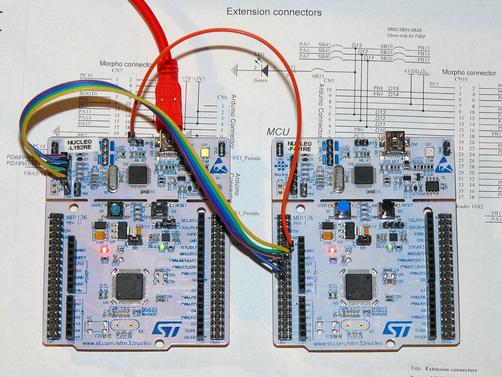
In my test results that just five wires (if you do not use Serial):

| St-link part(left Nucleo) | rest of Nucleo (right Nucleo) | signal |
|---|---|---|
| CN4 pin 2 | CN7 pin 15 | SWCLK |
| CN4 pin 3 | CN7 pin 19 | GND |
| CN4 pin 4 | CN7 pin 13 | SWDIO |
| CN4 pin 5 | CN7 pin 14 | NRST |
| JP1 left pin | CN7 pin 12 | +3V3_ST_LINK |
Programming and testing programs run entirely properly in this combination. Of course, CPU power supply can be solved in another way. Here is powered from 3.3V St-link, because it is so easy for me. For this test, in the right Nucleo it is open jumper CN12 (because not powered St-link bother NRST line), but in your situation it does not matter.
Hi, thank you for the image but I'm sorry. It doesn't works. I've connected the boards as your schema but STLink always says "SWD ERROR". https://www.dropbox.com/s/l304xbxmgl9oqow/Nucleo_f401re_Cutted.jpg
posted by 07 May 2015For me, this situation is incomprehensible. I also used this wiring diagram, for programming by Nucleo a variety of standalone PCBs with STM32 chips, even other types of STM32 than the original Nucleo set. And visibility by ST-Link and programming via a virtual disk or by ST-Link Utility was without any problems.
Maybe somewhere there is no connection or a short circuit. Have you checked the voltages on the target? Especially Vdd and NRST. And also continuous connectivity SWCLK signals and SWDIO, and whether they have somewhere short circuit (eg. in a place of cut-off)?
posted by 07 May 2015