Important changes to forums and questions
All forums and questions are now archived. To start a new conversation or read the latest updates go to forums.mbed.com.
7 years, 1 month ago.
TextLCD - PCF8574 Backpack - Nucleo L476RG
I'm trying to use the TextLCD-enhanced library, found here https://developer.mbed.org/users/wim/notebook/textlcd-enhanced/, to drive a 16x2 LCD (based on HD44780) through a PCF8574T backpack
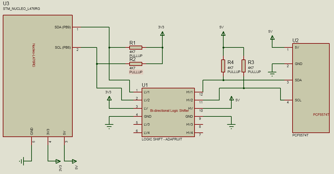
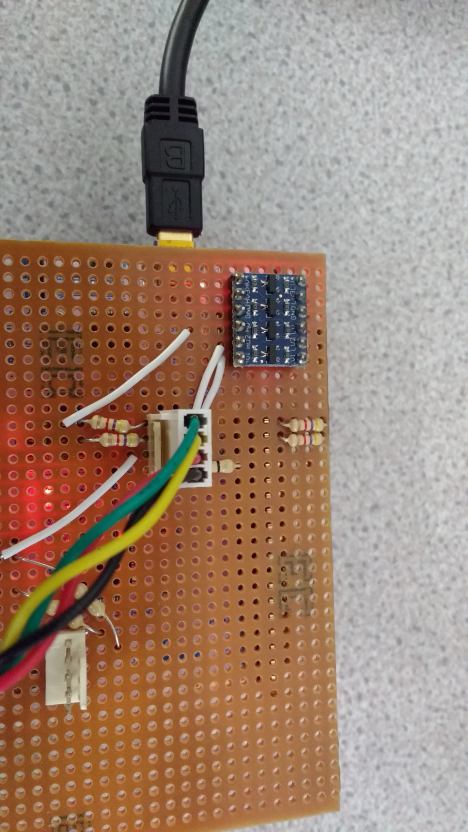
As the device is 5V i'm using a level shiftier similar to the one here: https://shop.pimoroni.com/products/sparkfun-logic-level-converter-bi-directional
I've also used a zero ohm resistor to connect RW to VSS as well as 4K7 pullup resistors on the SDA and SCL lines as mentioned in the textLCD documentation
Despite all this I cant get anything displaying on the LCD. I've checked for common issues such as changing the 7 bit address (0x20 in my case) to 8 bit (0x40) as well as changing the I2C slave type in LCD_config.h (I've tried all the different pinouts there of which none work). I've also tried modifying the default pinout to match the backpack I'm using which from testing with a multimeter I have found to have the following pinout:
_______
| LCD PINS | PCF PINS |
| ____ | ___ |
| EN | 2 |
| RW | 1 |
| RS | 0 |
| D4 | 4 |
| D5 | 5 |
| D6 | 6 |
| D7 | 7 |
| BL | 3 |
| ____ | ___ |
I'm using a nucleo-l476RG. The I2C can be see as working as I've also used some scanner code found here: https://developer.mbed.org/users/martinsimpson/code/ic2_test_bus/ which successfully reports back the LCD address (also verified as Ive changed the address and used different LCDs and it reports the correct address each time)
The LCD is verified as working as using an arduino with the liquidcrystal_I2C library the backpack functions with no problems.
The code i'm trying to run to output to the LCD is
LCD Hello World code taken from library plus I2C scan code
// Hello World! for the TextLCD

#include "mbed.h"
#include "TextLCD.h"


#define Device_Name_ADDR   (0xEE) // Device You Wish to Use Address - using i2c Address
#define WRITE              (0x00) // i2c Write bit
#define READ               (0x01) // i2c Read bit


// Host PC Communication channels
Serial pc(USBTX, USBRX); // tx, rx

// I2C Communication
I2C i2c_lcd(I2C_SDA, I2C_SCL); // SDA, SCL

// SPI Communication
//SPI spi_lcd(p5, NC, p7); // MOSI, MISO, SCLK

//4-bit bus
//TextLCD lcd(p15, p16, p17, p18, p19, p20, TextLCD::LCD16x4); // rs, e, d4-d7 ok
//TextLCD lcd(p15, p16, p17, p18, p19, p20, TextLCD::LCD20x2); // rs, e, d4-d7 ok
//TextLCD lcd(p15, p16, p17, p18, p19, p20, TextLCD::LCD20x4); // rs, e, d4-d7 ok
//TextLCD lcd(p15, p16, p17, p18, p19, p20, TextLCD::LCD24x4); // rs, e, d4-d7 ok
//TextLCD lcd(p15, p16, p17, p18, p19, p20, TextLCD::LCD24x2); // rs, e, d4-d7 ok
//TextLCD lcd(p15, p16, p17, p18, p19, p20, TextLCD::LCD40x2); // rs, e, d4-d7 ok

//I2C Portexpander PCF8574
TextLCD_I2C lcd(&i2c_lcd, 0x40, TextLCD::LCD16x2); // I2C bus, PCF8574 Slaveaddress, LCD Type ok
//TextLCD_I2C lcd(&i2c_lcd, 0x42, TextLCD::LCD16x2, TextLCD::WS0010); // I2C bus, PCF8574 addr, LCD Type, Ctrl Type

//I2C Portexpander MCP23008
//TextLCD_I2C lcd(&i2c_lcd, MCP23008_SA0, TextLCD::LCD16x3G, TextLCD::ST7036_3V3); // I2C bus, MCP23008 Slaveaddress, LCD Type, LCDTCtrl=ST7036

//SPI Portexpander SN74595
//TextLCD_SPI lcd(&spi_lcd, p8, TextLCD::LCD24x4D; TextLCD::KS0078); // SPI bus, CS pin, LCD Type ok
//TextLCD_SPI lcd(&spi_lcd, p8, TextLCD::LCD40x2); // SPI bus, CS pin, LCD Type ok
//TextLCD_SPI lcd(&spi_lcd, p8, TextLCD::LCD40x4); // SPI bus, CS pin, LCD Type ok

//Native I2C
//TextLCD_I2C_N lcd(&i2c_lcd, ST7032_SA, TextLCD::LCD16x2, NC, TextLCD::ST7032_3V3); // I2C bus, Slaveaddress, LCD Type, BL=NC, LCDTCtrl=ST7032_3V3
//TextLCD_I2C_N lcd(&i2c_lcd, PCF2116_SA0, TextLCD::LCD12x4D, NC, TextLCD::PCF2116_3V3); // I2C bus, Slaveaddress, LCD Type, BL=NC, LCDTCtrl=PCF2116_3V3
//TextLCD_I2C_N lcd(&i2c_lcd, PCF2116_SA0, TextLCD::LCD24x2, NC, TextLCD::PCF2116_3V3); // I2C bus, Slaveaddress, LCD Type, BL=NC, LCDTCtrl=PCF2116_3V3
//TextLCD_I2C_N lcd(&i2c_lcd, SSD1803_SA1, TextLCD::LCD20x4D, NC, TextLCD::SSD1803_3V3); // I2C bus, slaveaddress, LCDType=LCD16x2, BL=NC, LCDTCtrl=SSD1803A =Ok

//Native SPI 4 wire, 8 bits
//TextLCD_SPI_N lcd(&spi_lcd, p8, p9);    // SPI bus, CS pin, RS pin, LCDType=LCD16x2, BL=NC, LCDTCtrl=ST7032_3V3

//Native SPI 3 wire, 10bits
//TextLCD_SPI_N_3_10 lcd(&spi_lcd, p8, TextLCD::LCD16x2, NC, TextLCD::WS0010); // SPI bus, CS, LCDType=LCD16x2, BL=NC, LCDTCtrl=WS0010
//TextLCD_SPI_N lcd(&spi_lcd, p8, p9, TextLCD::LCD16x3G, NC, TextLCD::ST7036_3V3); // SPI bus, CS pin, RS pin, LCDType=LCD16x2, BL=NC, LCDTCtrl=ST7036

//Native SPI 3 wire, 24 bits, SSD1803A
//TextLCD_SPI_N_3_24 lcd(&spi_lcd, p8, TextLCD::LCD20x4D, NC, TextLCD::SSD1803_3V3); // SPI bus, CS pin, LCDType=LCD20x4, BL=NC, LCDTCtrl=SSD1803A =Ok

char ucdata_write[2];
short count=0;

void I2CScan (void);

void I2CScan()
{
	unsigned int uibaudrate=115200;
   pc.baud(uibaudrate);

   unsigned int uifrequency=400000; //400KHz for i2c Max
   i2c_lcd.frequency (uifrequency);

   pc.printf("\n\rHello World ");
   pc.printf("at %u BAUD and %uKHz i2c Frequency\n\r",uibaudrate,uifrequency/1000);
   pc.printf("Using mbed.org Martin\n\r");


   ucdata_write[0]=0;ucdata_write[1]=0;

   for (int Device_Adress=0;Device_Adress<=0xFE;Device_Adress+=2)//Stepping in 2 Because Read/Write use LSB
   {
   if (!i2c_lcd.write((Device_Adress|WRITE), ucdata_write, 1, 0))// Check for ACK from i2c Device NB I am 'ORing' the Write Bit
       {
           pc.printf("ACK from the Device at Address %#4x\n\r",Device_Adress);
           count=count+1;
           wait(2);
       }
       else
       {
           //Left the following in for development/Future coding
           //pc.printf("\n\rCannot get an ACK from the Device check connections!\n\r");
           //lcd.printf("No ACK from\nDevice!");
       }
   }
   pc.printf("\n\r %d Devices have been detected!\n\r",count);
	 pc.printf("\n\r");
}

int main() {

		I2CScan();

    pc.printf("LCD Test. Columns=%d, Rows=%d\n\r", lcd.columns(), lcd.rows());

    for (int row=0; row<lcd.rows(); row++) {
      int col=0;

      pc.printf("MemAddr(Col=%d, Row=%d)=0x%02X\n\r", col, row, lcd.getAddress(col, row));
//      lcd.putc('-');
      lcd.putc('0' + row);

      for (col=1; col<lcd.columns()-1; col++) {
        lcd.putc('*');
      }

      pc.printf("MemAddr(Col=%d, Row=%d)=0x%02X\n\r", col, row, lcd.getAddress(col, row));
      lcd.putc('+');
    }

// Show cursor as blinking character
    lcd.setCursor(TextLCD::CurOff_BlkOn);

// Set and show user defined characters. A maximum of 8 UDCs are supported by the HD44780.
// They are defined by a 5x7 bitpattern.
    lcd.setUDC(0, (char *) udc_0);  // Show |>
    lcd.putc(0);
    lcd.setUDC(1, (char *) udc_1);  // Show <|
    lcd.putc(1);
    lcd.setUDC(2, (char *) udc_2);
    lcd.putc(2);
    lcd.setUDC(3, (char *) udc_3);
    lcd.putc(3);
    lcd.setUDC(4, (char *) udc_4);
    lcd.putc(4);
    lcd.setUDC(5, (char *) udc_5);
    lcd.putc(5);
    lcd.setUDC(6, (char *) udc_6);
    lcd.putc(6);
    lcd.setUDC(7, (char *) udc_7);
    lcd.putc(7);
}
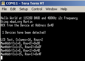
Serial output:
Schematic for hardware:
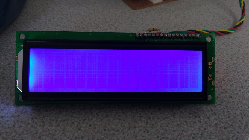
LCD Display:
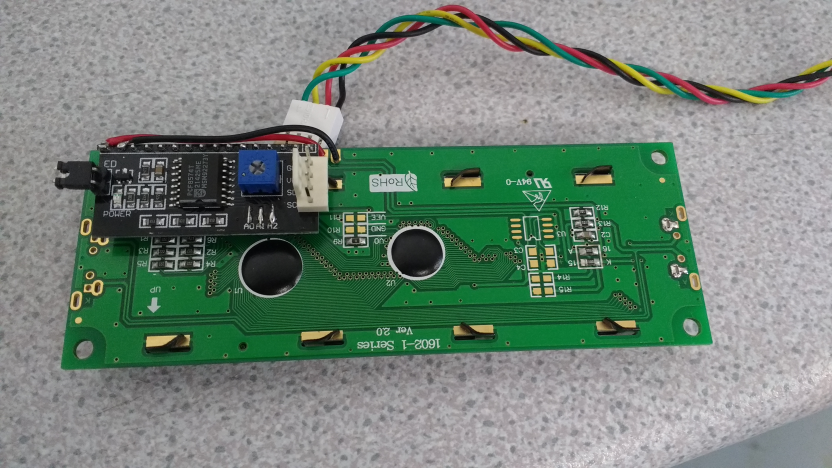
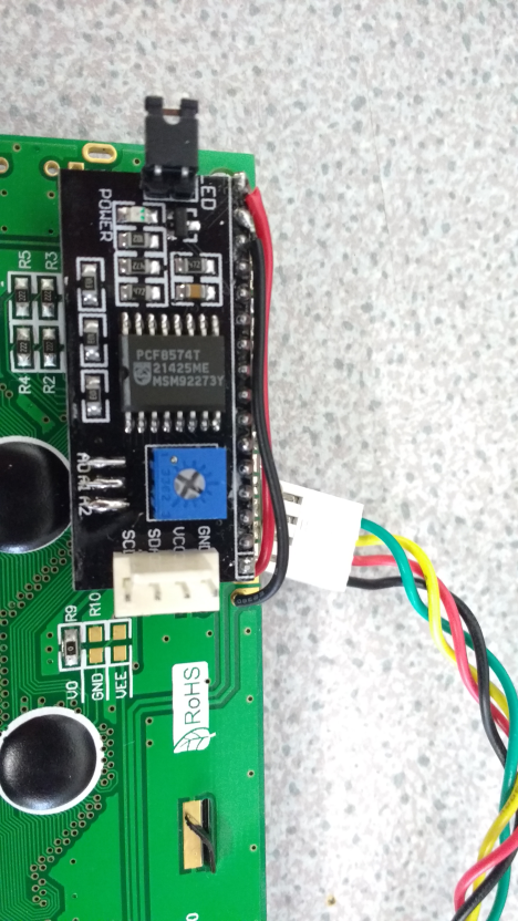
PCF Backpack:
Level Shifter:
Any help appreciated,
Andy
2 Answers
7 years, 1 month ago.
In checking the datasheet for the I2C GPIO expander (PCF8574), the I2C clock rate is too high in your code. The max supported speed is 100 khz (your code has 400 khz).
Lower this clock value to be 100 khz and test again.
Reference: http://www.ti.com/lit/ds/symlink/pcf8574.pdf
Table 6.6
Same max speed with the NXP version of this device:
Update:
For now, forget about the LCD display interfacing and confirm the I2C GPIO expander code is working correctly.
Try this demo: http://blog.rareschool.com/2012/03/pcf8574-i2c-and-mbed.html
https://developer.mbed.org/cookbook/PCF8574-I2C-IO-Expander
Be sure you can toggle the GPIO pin on the port expander using the mbed code to move forward. Once this is working then debug the LCD code and pinout to the same port expander.
Update 2
The LCD display wiring to the PCF IC does not appear to be correct. Review this schematic for your PCF PCB. Leave the wiring for the LCD display as shown on this webpage:
http://www.electroschematics.com/12459/arduino-i2c-lcd-backpack-introductory-tutorial/
Concerned about RS, E and RW LCD pins. Clarify where pin 0 on the PCF device is located ? If you alter the PCF to LCD pin mappings then you must also alter the mbed related code that manipulates the same port pins else the code will break. It will be best to follow exactly one of the working LCD examples from mbed that use the same port expander and use the same LCD pinout.
At this stage, your I2C to PCF operation appears to be solid but the LCD to PCF wiring needs to be reviewed. You may be toggling the proper pins on the PCF but they are not reaching the LCD so you are shooting blanks.
Then proceed to test again.
Update 3
Agree with Wim. Nice catch ! Do believe that the backpack is not properly oriented for this LCD display. After a few comparisons of the LCD and I2C backpack pics, believe the issue is that the LCD display is not the typical industry popular top left side hole mounting. Instead your LCD appears to be upside down in the pic and is bottom right side mounting.
Best to review where is the SQUARE solder pad on the LCD and also on the I2C backpack. The SQUARE pad on PCB layouts denotes pin # 1 to assist with alignment of the mating parts. Share the datasheets for your LCD display (if available) but looks like this is the issue. Carefully remove the solder from each pin to remove the back back and before you attach onto the LCD display, verify that the module is working correctly - such as checking where is the ground on the LCD pins for this back pack ? where does the 5 volt feed land on the LCD pins with this back pack ? You could even attempt to use the mbed code without the lcd display attached and use a meter in logic probe mode to see if the some of the PCF ports pins are toggling as they should. You may be ok here to just correct the orientation of the back pack but in the worse case, these parts are not too expensive to resource. My bet is that you will be fine once you fix this orientation.
http://telecnatron.com/modules/pcf8574-i2c-lcd-driver/
The consensus is that the I2C port pins on the PCF module should end up facing the outside of the LCD module edge. Your LCD display is the odd one and it is very easy to get confused. Summary - remove the PCF module and rotate it 180 degrees and mount to the LCD display. With this rotation, the PCF module will be south of the LCD display and not directly behind the display. Do share the datasheet for your LCD display so we can all confirm we have this right.
From the internet and the above webpage, pin # 1 on a standard LCD display is the top left for this model of display. This means that the PCF back pack is also pin # 1 above the Back Light shorting jumper. From your BLUE LCD display, believe that pin # 1 is bottom left when oriented properly (see the UP text on your backside of the PCB) - meaning you have your display upside down in the photo. Sorry for the rambling but believe Wim is spot on. Good luck and do test again after correcting.
Hi, thanks for that, I've just tested that using 100k and i'm still only getting white squares on the display so it doesn't seem like thats the issue
posted by 10 Mar 20177 years, 1 month ago.
I am suspicious about the way the backback is mounted to the lcd. It looks like you have mounted it in reverse. Check where pin 1 of the lcd is indicated. That should be connected to pin 1 of the backpack, which is identified by a white square box around the pin. The backlight may be working because you have separate wires from the backpack to pin 15 and 16 of the lcd. Pin 1 of the lcd is usually in the lower left and/or upper left corner of the display module when looking at it from the front with the characters upright. There are some displays with Different pinout, but this is the most common. Mounting the backpack in reverse means that the pcf8574 is detected at 0x40 but the lcd is not powered, shows no dark rectangles when the contrast is changed and may have been damaged...
The solution to this problem was that all of the 4 PCF backpacks I had tried were faulty / incorrect pinout. Found another PCF backpack from a different box and is all working fine. Re comments about the mounting, I did have the LCD upside down however the mounting of the backpack is correct as confirmed from the pinout of the datasheet of the winstar LCD module. Thanks all for your help, Andy
posted by Andrew West 11 Mar 2017There are multiple versions of backpacks even when the look similar. Check my notebook page and select the correct one. Differences are related to alternate wiring between the PCF8574 and the LCD, different default addresses (eg 0x4E instead of 0x40) or a different version of the portexpander (PCF8574A instead of PCF8574) with a different base address.
posted by Wim Huiskamp 17 Mar 2017