Important changes to forums and questions
All forums and questions are now archived. To start a new conversation or read the latest updates go to forums.mbed.com.
9 years, 11 months ago.
Using PA_2 and PA_3 as DigitalOut
Hello,
I would like to use PA_2 (D1) and PA_3 (D0) as DigitalOuts to use an Arduino shield. However these pins are used by Serial2, and I think that it is by default the 'stdout'. How could I close (or 'delete', or change) this predefined stdout config.
Thanks.
Carlos.
Question relating to:

3 Answers
9 years, 10 months ago.
Hello,
If you want to use the PA_2/PA_3 pins you need to close SB62/SB63 and open SB13/SB14 solder bridges.
To reprogram the F401RE device, you will need to manually wire the signals from CN4 connector to the F401RE device (SWCLK CN7 pin 15 and SWDIO CN7 pin13).
More info in the user manual:
http://www.st.com/st-web-ui/static/active/en/resource/technical/document/user_manual/DM00105823.pdf
Regards.
Hello, OK, if I've understood after reading the manual, SB62-63 connect PA2 and PA3 of F401 to Arduino connector, and SB13-14 connect PA2 and PA3 to USB virtual serial port. So, to use D0 and D1 outputs, I have to close SB62-63 and open SB13-14 as you say. But, I don't undertand why I'll have problems to reprogram with these changes. And more important, from 'mbed' point of view, I believe that 'stdout' goes on using USART2 of F401, so how can I remove (or change) the predefined stdout used bay 'mbed' software?.
Thanks.
Carlos.
posted by 26 May 20149 years, 10 months ago.
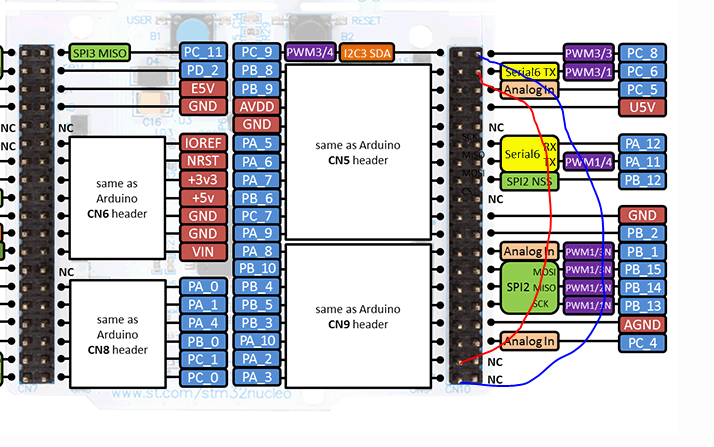
You can connect directly PA_2 and PA_3 to other pins like on picture. But there is 3.3 V on PC's pins. Although most of Arduino shields should be works.

9 years, 2 months ago.
For use PA_2 (D1) and PA_3 (D0) as DigitalOuts to use an Arduino shield you have to do this:
close SB62/SB63 and mount 3k3 on SB13/SB14.
doing so will operate the digital outputs PA_2 (D1) and PA_3 (D0) and at the same time the programmer st-link will continue to work.
