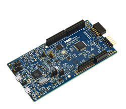
NXP LPCXpresso54114
LPCXpressoV3 development board for NXP LPC5411x series MCUs
Overview
The LPC5411x are ARM Cortex-M4 based microcontrollers for embedded applications. These devices include an optional ARM Cortex-M0+ coprocessor, up to 192 KB of on-chip SRAM, up to 256 KB on-chip flash, Full Speed USB device interface, a DMIC subsystem with dual-channel PDM microphone interface and I2S, five general-purpose timers, one versatile timer with PWM and many other capabilities (SCTimer/PWM), one RTC/alarm timer, one 24-bit Multi-Rate Timer (MRT), a Windowed Watchdog Timer (WWDT), eight flexible serial communication peripherals (each of which can be a USART, SPIs, or I2C interface), and one 12-bit 5.0 Msamples/sec ADC, and a temperature sensor.
Firmware update required
Please make sure you have updated your LPCXpresso to the latest firmware to enable the mbed flash disk interface


In an always-on application, these MCUs operate in a power-down mode, listening for incoming data, which when available, can wake either core to acquire or process the information. When in an active mode, developers can optimize power efficiency and throughput by choosing between the power-efficient Cortex-M0+ core for data collection, aggregation, and system task management, or the Cortex-M4 core, which can complete processor intensive algorithms, such as sensor fusion more quickly helping to reduce power consumed.
The pinout diagrams above shows the commonly used interfaces and their locations. The "SHT" designation refers to the sheet number(s) of the schematic related to each functional pin.
Features
- LPC54114J256BD64 device running at up to 100 MHz
- 100MHz Cortex-M4F and M0+
- 256KB flash, 192KB SRAM
- Flexcomm interfaces that support up to 8 serial peripherals, software selectable as I2C, SPI or USART. Two of these interfaces can be I2S
- Crystal-less, full speed USB interface
- Dual DMIC interface
- 12-bit, 12 channel ADC with sample rates up to 5MS/sec
- Integrated temperature sensor
- Five general purpose counter/timers, state-configurable timer with 8 input and 8 output functions, 32-bit RTC, Windowed watch dog timer, multi-channel, multi-rate timer for repetitive interrupt generation
- On-board high-speed USB based debug probe and external debug probe option
- Tri-color LED, target Reset, ISP & interrupt/user buttons for easy testing of software functionality
- Expansion options based on Arduino UNO and Pmod™, plus additional expansion port pins
- On-board 1.8 V and 3.3 V regulators plus external power supply option
- 8 Mb Macronix MX25R SPI flash
- Built-in MCU power consumption and supply voltage measurement
- UART, I²C and SPI port bridging from LPC54114 target to USB via the on-board debug probe
- FTDI UART connector
Getting Started with mbed
1. Connect your microcontroller to a PC
Use the USB lead to connect your mbed to a PC. The status light will come on, indicating it has power. After a few seconds of activity, the PC will recognise the mbed Microcontroller as a standard USB drive.
 |  |
| Windows 10 example | Mac OS X example |
2. Click the PRODINFO.HTM link to get logged in
Go to the new USB Drive, and click PRODINFO.HTM to open it in a web browser.
If you do not have an mbed account, choose "Signup", and create your mbed Account. Otherwise, log in with your normal username and password.
This will give you access to the website, tools, libraries and documentation.
PC Configuration
Your mbed Microcontroller can appear on your computer as a serial port. On Mac and Linux, this will happen by default. For Windows, you need to install a driver:
Windows
See Windows-serial-configuration for full details about setting up Windows for serial communication with your mbed Microcontroller
From a host PC to communicate with mbed you will need a terminal application. This allows the mbed Microcontroller to print to your PC screen, and for you to send characters back to your mbed.
- Terminals - Using Terminal applications to communicate between the Host PC and the mbed Micrcontroller
Some terminal programs (e.g. TeraTerm) list the available serial ports by name. However, if you do need to know the identity of the serial port so that you can attach a terminal or an application to it:
| Windows | Mac | Linux | ||||
| Find the identity of the COM port by opening ''Device Manager''. To do this navigate ''Start -> Control Panel -> System -> Hardware -> Device Manager''. | To find the device name under Mac OS X, use the command ''ls /dev/tty.usbmodem*'' | To find the device name under Linux, use the command ''ls /dev/ttyACM*'' | ||||
 |  |  |
Downloading A program
1. Save a program binary (.bin) to the Platform
Download the appropriate "Hello World!" binary:
- lpcxpresso54114: HelloWorld_lpcxpresso54114.bin
Note: the source code for this program will be seen in the next section.
Save the program binary file to your mbed Microcontroller Disk, just like you would with a normal USB disk. The Status LED will flash as the PC writes the file to the Microcontroller disk. The file is now consumed.
2. Press the Reset Button
When the Reset Button in pressed, the microcontroller will be reset and the last programmed application will begin to run.
3. Hello World!
The Microcontroller is now running the program; flashing the LED forever! If you reset the Microcontroller, or disconnect and reconnect the power, the program will simply restart.
Hello World!
[Repository '/teams/mbed-os-examples/code/mbed-os-example-blinky/' not found]
Where Next
Follow the guide to creating your own programs using the online compiler
Technical Reference
Schematics
Data Sheets
Interface Firmware
You need to log in to post a discussion
To compile a program for this board using Mbed CLI, use lpc54114 as the target name.
 Mbed Enabled
- Baseline
Mbed OS support
- Mbed OS 5.10
- Mbed OS 5.11
- Mbed OS 5.12
- Mbed OS 5.13
- Mbed OS 5.14
- Mbed OS 5.15
- Mbed OS 5.6
- Mbed OS 5.7
- Mbed OS 5.8
- Mbed OS 5.9
- Mbed OS 6.0
- Mbed OS 6.1
- Mbed OS 6.10
- Mbed OS 6.11
- Mbed OS 6.12
- Mbed OS 6.13
- Mbed OS 6.14
- Mbed OS 6.15
- Mbed OS 6.2
- Mbed OS 6.3
- Mbed OS 6.4
- Mbed OS 6.5
- Mbed OS 6.6
- Mbed OS 6.7
- Mbed OS 6.8
- Mbed OS 6.9
Example programs
CMSIS support
Find documentation, software examples and the CMSIS Board Support Pack.
NXP LPCXpresso54114 on keil.arm.com