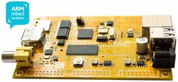
VK-RZ/A1H
VK-RZ/A1H from Vekatech is an mbed Enabled™ platform which allows you to build a diversity of powerful applications in a wide range of embedded tasks.
Overview
This starter kit uses a powerful ARM® Cortex™-A9 single-chip microcontroller from Renesas Electronics, along with the integrated peripheral functions required to configure a system.
For more information visit our team page:
- The core includes:
- 32-KB L1 instruction cache
- 32-KB L1 data cache
- 128-KB L2 cache
- Integrated on-chip peripheral functions and interfaces:
- 10-MB large-capacity RAM
- 128-KB data-retention RAM ( shared with the large-capacity RAM )
- multi-function timer pulse unit 2, OS timer, realtime clock
- motor control PWM timer
- UART, UART with FIFO, I2C, SPI, SPI multi I/O bus controller, CAN, LIN
- serial sound interface, sound generator, CD-ROM decoder
- A/D converter, SCUX
- media local bus, SD host interface, MMC host interface
- NAND flash memory controller
- IEBus™ controller, Renesas SPDIF interface
- Ethernet controller, EthernetAVB
- USB 2.0 host/function
- digital video decoder, video display controller 5
- dynamic range compression, image renderer, image renderer for display
- display out comparison unit
- Renesas graphics processor for OpenVG™
- JPEG codec unit, capture engine unit, pixel format converter
- interrupt controller modules, general I/O ports


Features
- Renesas RZ/A1H - (R7S721000VCBG)
- High performance ARM® Cortex™-A9 Core
- 32KB Instruction cache, 32 KB Data cache, 128KB L2 cache
- including NEON and FPU
- 400MHz, 10MB On-Chip RAM
- 2xUSB Host/Device Interface, 1xEthernet
- 5xSPI, 4xI2C, 6xI2S, 8xUART, 8x12-bits ADC, 16xPWM, 16xTIOC, 5xCAN, 2xLCDC, 2xCamera Input, 1xSPDIF
- 2xSD, 2xMMC, 1xNAND, 115xGPIOs
- High performance ARM® Cortex™-A9 Core
- VK-RZ/A1H
- 32MB SDRAM
- ESMT on CS2 (M12L2561616A-6T)
- 32MB FLASH
- Spansion (2x S25FL128S)
- 4xSPI, 4xI2C, 2xI2S, 5xUART, 7x12-bits ADC, 13xPWM, 15xTIOC
- 1xSD, 1xSPDIF, 78xGPIOs
- 4xCAN
- CAN1 (via transceiver TJA1040)
- 2xUSB Host/Device Interface
- 1xEthernet
- mac (PHY SMSC LAN8710A)
- 1xCamera Input
- analog (via VIN1)
- digital (via DV1)
- 1xLCDC
- serial (via LVDS)
- paralel (via LCD0)
- On-board Debug and Programming Interface Chip - (LPC11U35FHI33/501)
- [USB MSC] Drag-n-drop programming
- [USB CDC] USB Serial Port
- [USB HID] CMSIS-DAP
- SWD (optional debugging for LPC11U35)
- On-board JTAG Interface for RZ/A1H (optional alternative to CMSIS-DAP)
- Power:
- mbed debug USB
- External Supply: 5V @ 0.5 - 1A
- Board
- Material: FR-4, 2.0 mm
- Dimensions: 105.0mm x 74.0mm
- 32MB SDRAM
Firmware
1. Close jumpers JP1 & JP3 (Boot from Flash).
2. Power up the board through mbed debug interface.
3. Wait appearance of the MBED disk.
4. Drag & drop the new firmware in MBED disk.
5. Press reset button.
The alternative flash programming procedure (through the SD Card) still works. In the earlier (not mbed compatible) versions of VK-RZ/A1H, this was the only way for programming without using well known external tools (JTAG debuggers & falshers).
Getting Started with mbed
1. Connect your microcontroller to a PC
Use the USB lead to connect your mbed to a PC. The status light will come on, indicating it has power. After a few seconds of activity, the PC will recognise the mbed Microcontroller as a standard USB drive.
 |  |
| Windows XP example | Mac OS X example |
2. Click the MBED.HTM link to get logged in
Go to the new USB Drive, and click MBED.HTM to open it in a web browser.
If you do not have an mbed account, choose "Signup", and create your mbed Account. Otherwise, log in with your normal username and password.
This will give you access to the website, tools, libraries and documentation.
PC Configuration
Your mbed Microcontroller can appear on your computer as a serial port. On Mac and Linux, this will happen by default. For Windows, you need to install a driver:
Windows
See Windows-serial-configuration for full details about setting up Windows for serial communication with your mbed Microcontroller
From a host PC to communicate with mbed you will need a terminal application. This allows the mbed Microcontroller to print to your PC screen, and for you to send characters back to your mbed.
- Terminals - Using Terminal applications to communicate between the Host PC and the mbed Micrcontroller
Some terminal programs (e.g. TeraTerm) list the available serial ports by name. However, if you do need to know the identity of the serial port so that you can attach a terminal or an application to it:
| Windows | Mac | Linux | ||||
| Find the identity of the COM port by opening ''Device Manager''. To do this navigate ''Start -> Control Panel -> System -> Hardware -> Device Manager''. | To find the device name under Mac OS X, use the command ''ls /dev/tty.usbmodem*'' | To find the device name under Linux, use the command ''ls /dev/ttyACM*'' | ||||
 |  |  |
Downloading A program
1. Save a program binary (.bin) to the Platform
Download the appropriate "Hello World!" binary:
- VK-RZ/A1H: HelloWorld_blinky.bin
Note: the source code for this program will be seen in the next section.
Save the program binary file to your mbed Microcontroller Disk, just like you would with a normal USB disk. The Status LED will flash as the PC writes the file to the Microcontroller disk. The file is now consumed.
2. Press the Reset Button
When the Reset Button is pressed, the microcontroller will be reset and the last programmed application will begin to run.
3. Hello World!
The Microcontroller is now running the program; flashing LED1 forever! If you reset the Microcontroller, or disconnect and reconnect the power, the program will simply restart.
Hello World!
Import programmbed_blinky
The example program for mbed pin-compatible platforms
Last commit 08 Apr 2019 by  Mbed
Mbed
Where Next
Follow the guide to creating your own programs using the online compiler
Import programVK_RZ_A1H_LCD_demo
Lcd companion boards support (VKLCD50RTA & VKLCD70RT)
Last commit 16 Feb 2017 by ![]() Vekatech
Vekatech
Technical Reference
Power
- USB powered or Power jack powered 5.0 V / 1 A
- Current (active): < 450 mA
- Digital IO pins are 3.3v, 2mA each, 150mA max total
Schematics
Interface Firmware
To change the interface firmware (HDK firmware) use the HDK update jumper.
- There are two ways to use the on-board flash
- single flash mode (1 flash in 1bit bus)
- 1. Make sure JP1, JP3 & HDK jumpers are closed. (Boot from Flash).
- 2. Power up through mbed debug USB and wait appearance of the CRP DISABLED disk.
- 3. Delete existing firmware.bin in the CRP DISABLED disk.
- 4. Drag & drop lpc11u35_vkrza1h_if.bin in the CRP DISABLED disk.
- 5. Open HDK jumper and power cycle.
- 6. Note that the appeared MBED disk volume is now 16 MB and this is because only 1 of the flashes is used.
- dual flash mode (Both flashes in 4bit bus each)
To set this mode, FIRST the board must be in single flash mode.- 7. Make sure JP1, JP3 are closed (Boot from Flash).
- 8. Drag & drop VKRZ_A1H_sflash_boot_init_dual.bin (Pairing init procedure) in the 16 MB MBED disk.
- 9. Close HDK jumper and power cycle.
- 10. Wait appearance of the CRP DISABLED disk and delete existing firmware.bin.
- 11. Drag & drop lpc11u35_vkrza1h_sfdual_if.bin in the CRP DISABLED disk.
- 12. Open HDK jumper and power cycle.
- 13. Note that the appeared MBED disk volume is now 32 MB and this is because both flashes are used.
- single flash mode (1 flash in 1bit bus)
Note:
mbed SDK works in dual flash mode !!!
You need to log in to post a discussion
To compile a program for this board using Mbed CLI, use VK_RZ_A1H as the target name.

Silicon Partner
Renesas
Renesas Electronics Corporation (TSE: 6723), the world's number one supplier of microcontrollers, is a premier supplier of advanced semiconductor solutions including microcontrollers, SoC solutions and a broad range of analog and power devices.
 Mbed Enabled
- Baseline
Mbed OS support
- Mbed OS 5.10
- Mbed OS 5.11
- Mbed OS 5.12
- Mbed OS 5.13
- Mbed OS 5.14
- Mbed OS 5.7
- Mbed OS 5.8
- Mbed OS 5.9