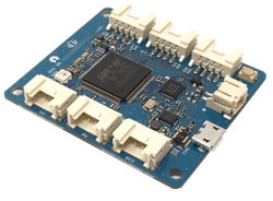
Seeed Wio LTE M1/NB1(BG96)
Seeed Wio LTE M1/NB1(BG96) is a complete board that enables quick prototyping of a variety of applications for the cellular Internet of Things.
MCU
STMicroelectronics STM32F439VI
Arm® Cortex®-M4 core with DSP and FPU, 2 MBytes Flash, 256 KBytes SRAM
Cellular module
Quectel BG96 LTE Cat M1 & Cat NB1 & EGPRS module
FDD-LTE: B1/ B2/ B3/ B4/ B5/ B8/ B12/ B13/ B18/ B19/ B20/ B26/ B28
TDD-LTE: B39 (for Cat M1 only)
EGPRS: 850/900/1800/1900Mhz
Note: BG96 module have several firmware variation to meet operators technical requirement such as IOT (interoperability testing). The firmware variation of the module depend on distribution channel.
| Distribution ch. | Supported Operator |
|---|---|
| SORACOM | KDDI |
| SoftBank | SoftBank |
| TBD | Sprint |
Pinout

Wio BG96 (shorten name of this board) have 6x Grove System connector. It is compatible with 3.3V interface grove modules. Some Grove modules were registered on Components. For non Grove peripherals, you can connect easily with "Grove to 4pin Female/Male Jumper" cables.
To turn-on 3.3V power supply to "3.3V-B" pins, please make power control pin HIGH like below.
DigitalOut GrovePower(GRO_POWR, 1);
On-board peripherals
For same power consumption purpose, some power supply for peripherals are controlled by GPIO.
RGB LED:
DigitalOut LEDPower(RGB_POWR, 1);
Sample code: https://os.mbed.com/teams/Seeed/code/Wio-example-blinky/
The LED on this board is SK6812MINI, intelligent LED chip. The control data pin is PB_1.
SD:
DigitalOut SDPower(PA_15, 1);
Sample code: https://os.mbed.com/teams/Seeed/code/Wio-example-sd-driver/
And the SPI pins connected to SD slot are MOSI: PC_12, MISO: PC_11, SCK: PC_10, CS: PD_0 as defined on sample code.
The instraction to install / remove SD/SIM cards are on here. https://seeedjp.github.io/Wiki/General/how_to_sim_tf-en
Known issues
- CTS/RTS connection is swapped from MCU native pin definition on v.ES version hardware. This causes a problem with Mbed OS 5.11. - Workaround
Boards which marked as v.ES2 solved this issue.
Interface
- 6x Grove connector (3.3V I/O)
- 2x Digital I/O
- 2x Analog Input ( can be used as Digital I/O )
- 1x UART ( can be used as Digital I/O )
- 1x I²C ( can be used as Digital I/O )
- Cellular antenna U.FL connector
- nano SIM card slot ( optional eSIM )
- DAPLink ( USB Micro-B connector )
- Li-Ion battery connector ( JST PH, charging current 690mA )
- Micro SD card slot
Microcontroller features
- STM32F439VI in LQFP100 package
- ARM®32-bit Cortex®-M4 CPU with FPU Adaptive real-time accelerator (ART Accelerator™) allowing 0-wait state execution from Flash memory
- 180 MHz max CPU frequency
- 2 MB Flash
- 256 KB SRAM
- TRNG (True random generator)
- Cryptographic acceleration: hardware acceleration for AES 128, 192, 256, Triple DES, HASH (MD5, SHA-1, SHA-2), and HMAC
- Up to 17 timers
- 3x SPI
- 3x I2C
- 4x USART
- 1x SAI (Serial Audio Interface)
- 3x 12-bit ADC
- 2x 12-bit DAC
Battery Operation
Wio BG96 includes a MP2617B monolithic switch mode battery charger with power path management for single-cell Li-ion batteries. The charge current is set by a resistor attached to the ISET pin on the MP2617B. The 3K Ohm resistor installed by default sets the charge current at 690mA which is tolerable for most typical batteries with a capacity greater than or equal to 690mAH. Please consult the MP2617B datasheet and the datasheet for your battery to ensure compatibility. The connector is JST PH, since there are no standard to use this connector for Li-Ion batteries, please take care about the polar.
The "CHG" LED next to Micro USB receptacle indicates battery charging status.
| LED Statues | Battery Statues |
|---|---|
| Blinking | No battery or error |
| ON | Charging |
| OFF | Charging complete |
Firmware Update
The latest Arm Mbed DAPLink interface firmware is available at (click the image):
![]()
Pre-installed DAPLink interface firmware is wio_bg96_interface_v251_20181110.bin
To check your firmware version and built date, open the MBED.HTM or DETAILS.TXT of your MBED disk in a text editor.
To update the firmware,
- Hold the reset button and power on it
- A CRP DISABLD disk will show
- On Windows, replace firmware.bin with the above firmware
- On Linux/Mac, use command: dd if={new_firmware.bin} of={firmware.bin} conv=notrunc
Resources

To compile a program for this board using Mbed CLI, use wio_bg96 as the target name.
Board Partner
Seeed
A hardware innovation platform for makers to grow inspirations into differentiating products.
Silicon Partner
ST
A world leader in providing the semiconductor solutions that make a positive contribution to people’s lives, both today and in the future.
 Mbed Enabled
- Advanced
- Baseline
Mbed OS support
- Mbed OS 5.11
- Mbed OS 5.12
- Mbed OS 5.13
- Mbed OS 5.14
- Mbed OS 5.15
- Mbed OS 6.0
- Mbed OS 6.1
- Mbed OS 6.10
- Mbed OS 6.11
- Mbed OS 6.12
- Mbed OS 6.13
- Mbed OS 6.14
- Mbed OS 6.15
- Mbed OS 6.2
- Mbed OS 6.3
- Mbed OS 6.4
- Mbed OS 6.5
- Mbed OS 6.6
- Mbed OS 6.7
- Mbed OS 6.8
- Mbed OS 6.9
Example programs