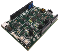
Arm V2M-Musca-S1
The Musca-S1 implementation of SSE-200 subsystem deploys two Cortex-M33 processor cores on Samsung Foundry 28FDS and is ready for evaluation of eMRAM-enabled IoT device with secure PSA Root-of-Trust (RoT). Musca-S1 can be used to prototype secure boot, on-chip storage, execution, and network device management through the Keil MDK, TF-M, Mbed OS Arm IoT software stack, and Pelion IoT platform integration. Musca-S1 is PSA Certified Level 1 and PSA Functional API certified.

Overview
The digital transformation is underway and driving the need for a new generation of Smart IoT Devices that are both secure and energy-efficient and the foundation to enabling our secure connected world.
Recognizing this need Arm and Samsung Foundry collaborated to create the industry’s 1st PSA Certified Arm-based Smart IoT Device demonstrator called Musca-S1 enabling secure eMRAM-enabled Root of Trust (RoT) and secure Root of Execution (RoE) IoT Device services.
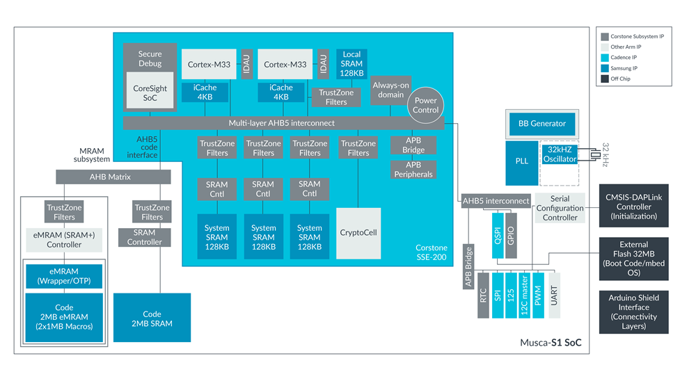
The Musca-S1 dual Arm Cortex-M33 test chip board architecture integrates the recommendations of Platform Security Architecture, (PSA) using the same subsystem as Musca-A, but with the addition of dual embedded MagnetoResistive Random Access Memory (eMRAM) and SRAM on-chip secure memory subsystems
Based on Arm’s Corstone-200 pre-verified subsystem with dual Cortex-M33 processor cores, AMBA AHB5/Trust Zone dual eMRAM and SRAM code memory subsystems, Samsung analogue IPs for control, Cadence and Arm peripheral interface IPs for extended network and cellular connectivity, Musca-S1 provides a series of silicon-proven insights for secure and energy-efficient IoT design on Samsung 28FDS FDSOI silicon.
Musca-S1 test chip demonstrates a combination of on-chip power control, Samsung Foundry’s Reverse Body Biasing (RBB) and eMRAM non-volatile memory power shutdown, allowing for testing and evaluation of new classes of highly energy-efficient, controlled IoT devices.
By combining Arm IP and software solutions on a single board, IoT designers can test and evaluate Arm end-to-end secure IoT solution, showcasing highly energy-efficient and secure IoT at scale. The Musca-S1 test chip board can further reduce costs and time-to-market by giving designers the flexibility to repurpose the reference design for future products.

Board Features
The development board contains the following components and systems:
- One Musca‑S1 test chip with CoreLink SSE-200 Subsystem for Embedded. The SSE-200
subsystem includes, but is not limited to, the following:
- CPU0: One 50MHZ Cortex‑M33 processor. Floating-point unit (FPU), DSP, no coprocessor.
- CPU1: One 200MHZ Cortex‑M33 processor. FPU, DSP, no coprocessor. Clock system enables operation at ×N speed of CPU0 processor. Body-bias enabled transistors for low-power mode.
- One 2KB instruction cache and one 2KB data cache for each processor.
- 4 × 128KB SRAM. One 128KB bank, SRAM3, functions as Tightly Coupled Memory (TCM), Tightly Coupled to CPU1 and operating at CPU1 clock speed.
- CryptoCell™-312 with 1Kbyte One Time Programming (OTP) emulated using simple registers reset by powerup reset only.
- Timer, Watchdog peripherals, and system control.
- The following on-chip blocks are outside the SSE-200 subsystem.
- 2MB Code SRAM.
- 2×1MB eMRAM.
- Clock system. Input clock sources from development board.
- Arduino Shield expansion with on-board level converters and a jumper link to enable the Shield
voltage to be either the SoC voltage, 1V8, or 3V3. Enables custom designs by providing the
following interfaces:
- UART/USART.
- I2S, three-channel, master only.
- SPI.
- I2C.
- PWM.
- 6-channel analog interface from the on-board combined ADC, DAC, and GPIO.
- 16 1V8 or 3V3 GPIO.
- 1Hz clock.
- On-board DAPLink that enables the following functionality over USB:
- Serial Wire Debug (SWD).
- USB Mass Storage Device (USBMSD) for uploading new firmware.
- USB serial port. The UART to the DAPLink does not support hardware flow control.
- Remote reset.
- On-board gyro sensor:
- MMA7660FC 3-axis orientation and motion detection sensor.
- I2C interface to test chip.
- On-board combined ADC/DAC/temperature sensor:
- AD5593.
- 6-channel 3V3 ADC/DAC/GPIO interface to Arduino Shield.
- Temperature indicator.
- Programmable boot select:
- 32MB On-board QSPI boot flash.
- 2×1MB on-chip boot eMRAM.
- 2MB on-chip Code SRAM, after being preloaded with execution code.
- Both Secure and Non‑secure access.
- Debug connector that provides access to:
- P-JTAG processor debug.
- Serial Wire Debug (SWD).
- User push-button:
- PBON On/Off push-button.
- nSRST: Cortex-M33 system reset and CoreSight component reset.
- ISP: Updates DAPLink firmware.
- RGB LED. Jumper connectors provide optional connections between the Arduino Expansion header and the Musca‑S1 test chip:
- Red LED connected to GPIO[2] pin, optional PWM0.
- Green LED connected to GPIO[3] pin, optional PWM1.
- Blue LED connected to GPIO[4] pin, optional PWM2.
- Status LEDs.
- 5V USB or battery power, selectable by slider switch:
- DAPLink 5V USB connector.
- CLN 523450, Lithium Ion, 3.7V, 950mAh (not supplied).
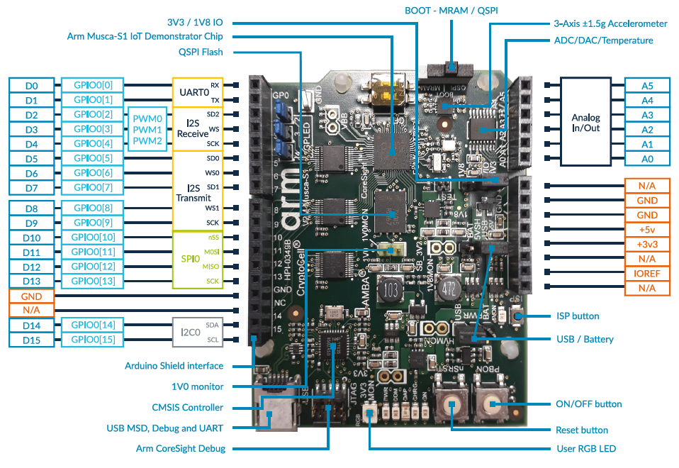
Board Pinout
The pinout diagram below shows the Arduino headers signals.

Technical Reference
Documentation
Interface Firmware
Firmware update required!
Please make sure you have updated your Musca S1 board to the latest firmware.
The instructions and the latest firmware for DAPLink are available here.
Press the PBON button to start!
By default, the Musca S1 board keeps the MCU switched off after a power-cycle.
You need to press the PBON button to run the application. This behaviour can be changed:
- Auto-start an application when the board is plugged-in. Drag and drop an empty file "auto_pwr.cfg" into the device
- Power-on the MCU when pressing the PBON push button: Drag and drop an empty file "hard_pwr.cfg" into the device
Known Issues
Please check issues reported on GitHub.
The Mbed Online Compiler is not supported with this board.
Please use Mbed Studio.
Example applications
You need to log in to post a discussion
