Hello, i am new to MBED's and i am trying to follow a simple tutorial but i am having trouble understanding and copying the demonstration as i do not want to run the program and destroy any hardware by placing the resistor in the incorrect place.
Sorry if this is a dumb question but i am only 15 and i am interested in electronics but i do not want to destroy any of the hardware. Any help would be greatly appreciated.
Here is my program below which i am trying to build, but i am having trouble with the hardware:
Program 1
#include "mbed.h

DigitalOut LED1(p10);
DigitalOut LED2(p11);
DigitalIn Switch(p12);

int main() {

	while (1) {

		if (Switch == 0) {
			LED1 = 0;     // Turn led1 off.
			LED2 = 1;     // Turn led2 on
			wait(0.5);
			LED2 = 0;
			wait(0.5);
		}


		else if (Switch == 1) {
			LED2 = 0;
			LED1 = 1;
			wait(0.5);
			LED1 = 0;
			wait(0.5);
		}
	}
}
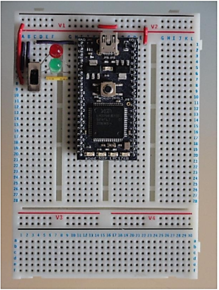
I am trying to replicate this diagram here but to the ports i specified in my program:

So for my program am i right in assuming:
The center of the switch is placed in p12 of the mbed.
Connect LED1's cathode to p10 and the anode to the current limit resistor - inline with 'G' on the breadboard
Connect LED2's cathode to p11 and the anode to the current limit resistor - inline with 'G' on the breadboard
Connect a wire directly from p12 to vout (Opposite side of breadboard (3.3v out))
Connect a wire directly from p11 to gnd (0v)
Connect a wire directly from p10 to gnd (0v)
Current a resistor to the same pin as both of the anodes of p11 and p12, and the otherside of the resistor as shown in the image. (E6)
Hello, i am new to MBED's and i am trying to follow a simple tutorial but i am having trouble understanding and copying the demonstration as i do not want to run the program and destroy any hardware by placing the resistor in the incorrect place.
Sorry if this is a dumb question but i am only 15 and i am interested in electronics but i do not want to destroy any of the hardware. Any help would be greatly appreciated.
Here is my program below which i am trying to build, but i am having trouble with the hardware:
Program 1
#include "mbed.h DigitalOut LED1(p10); DigitalOut LED2(p11); DigitalIn Switch(p12); int main() { while (1) { if (Switch == 0) { LED1 = 0; // Turn led1 off. LED2 = 1; // Turn led2 on wait(0.5); LED2 = 0; wait(0.5); } else if (Switch == 1) { LED2 = 0; LED1 = 1; wait(0.5); LED1 = 0; wait(0.5); } } }I am trying to replicate this diagram here but to the ports i specified in my program:
So for my program am i right in assuming:
The center of the switch is placed in p12 of the mbed.
Connect LED1's cathode to p10 and the anode to the current limit resistor - inline with 'G' on the breadboard
Connect LED2's cathode to p11 and the anode to the current limit resistor - inline with 'G' on the breadboard
Connect a wire directly from p12 to vout (Opposite side of breadboard (3.3v out))
Connect a wire directly from p11 to gnd (0v)
Connect a wire directly from p10 to gnd (0v)
Current a resistor to the same pin as both of the anodes of p11 and p12, and the otherside of the resistor as shown in the image. (E6)