My own base station design. It features:
- Ethernet (MagJack, SparkFun PRT-08534, MJF13T3L-KF06B3YG-0808)
- USB device (USB mini B female connector)
- USB host (USB A female connector, SMD version)
- MicroSD card (Hirose Electric DM3AT-SF-PEJ)
- Back-up coin battery (any Keystone Electronics coin cell holder with 0.807" through-hole pin spacing)
- Barrel jack (PJ-202A)
- Breadboard friendly
Schematic:
/media/uploads/frank26080115/mbed_basestation.pdf
PCB Preview:
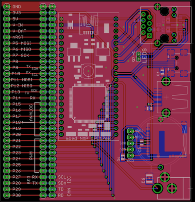
The holes on the left edge of the PCB is supposed to be pointing down, thus allowing you to plug it into a breadboard. The large gap is large enough to clear the width of the power rails of a breadboard.
The MicroSD card is not actually directly connected to the mbed, instead I give you the freedom to choose which SPI port you'd like to use. An optional pull-up resistor can be added to the CS signal of the MicroSD card. A 0.1 uF decoupling capacitor is required near the MicroSD card's power and ground.
The MagJack's LEDs are connected to a configurable jumper, you can choose for the LEDs to be connected to 3.3V or GND, and then you are free to connect the two LEDs to any pins on the mbed. The LEDs on the MagJack needs two current limiting resistors, the values of which depends on your brightness preferences. Two 1 uF capacitors should be connected to the center-taps of the MagJack transformers.
The back-up battery is installed on the bottom of the board.
The barrel jack has a capacitor footprint near its positive pin, you should decide on the value of that capacitor to suit your application. For example, connecting a rechargeable battery to the barrel jack would require a different capacitor than using a AC to DC wall adapter.
Most components are 0805 components on both the top side and bottom side. This board is very easy to assemble by hand, I don't plan on manufacturing them so components on both sides is perfectly fine.
Version 1
Eagle 5.10 files (for reference only, do not attempt to replicate, as version 2 is provided below) : /media/uploads/frank26080115/mbed_basestation_src_v1.zip
Pictures:
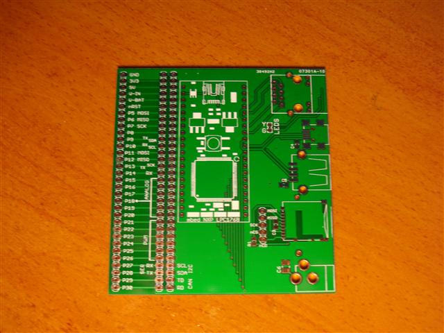
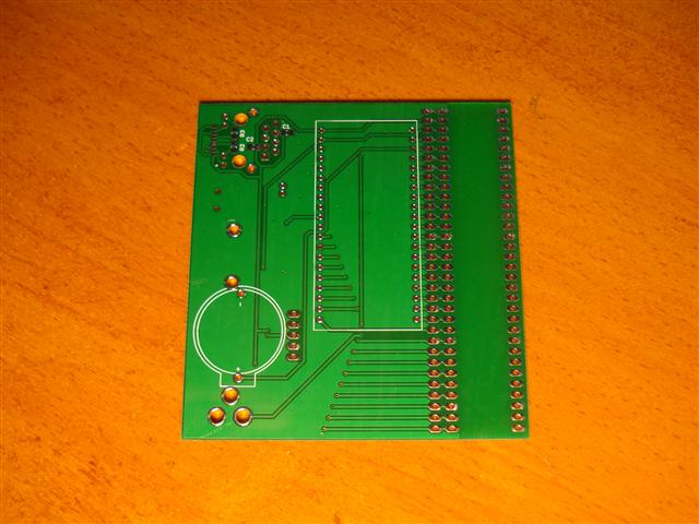
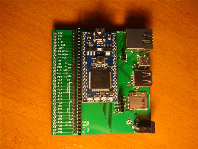
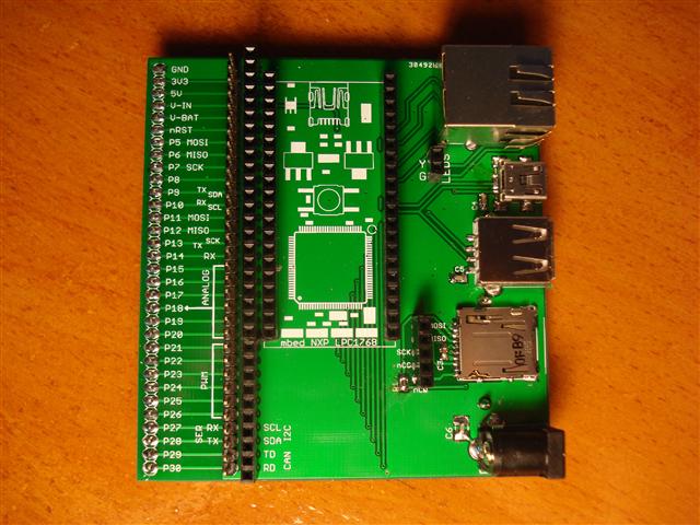
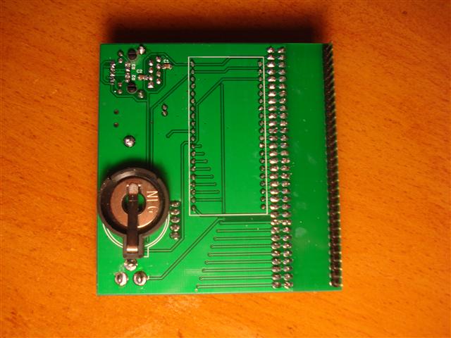
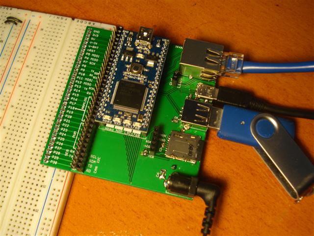
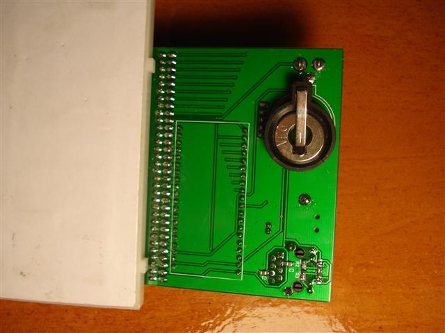
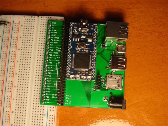
Ten bare PCBs were ordered from ITead Studio on March 6 and arrived (I live near Toronto) on March 18. Upon assembling it, I tested it by doing the following:
- Run a HTTP server demo
- Read files from the MicroSD card using a Petite FatFs demo
- Read files from a 2 GB USB drive using MSC USB host, however this failed for a 8 GB drive (it was able to enumerate the drive but was not able to use the file system).
- Run a USB Mouse demo
- Run the HTTP server while using a 12V DC power supply (instead of USB) and checked the expected voltages around the board
Notes and Errata for V1
- The footprint for the USB host (female A type) connector provided in the SparkFun Eagle library did not match the physical component purchased from them, the spacing between the outer pads are narrower than the spacing between the actual component's pins. The amount is only about one millimeter and so it is still usable.
- The two holes provided for the MagJack's LEDs are slightly narrower than 0.1", however anything 0.1" will still fit there.
- The holes provided for the mbed's footprint are good for female headers, but not male headers, so you cannot solder the mbed directly into this PCB.
- The pin labeling near the pin "GND" on the mbed itself may cause confusion as some of them are not aligned with the base-station's PCB silkscreen, please follow the base-station's silkscreen labels, not the labeling on the mbed itself.
- The MicroSD card holder footprint is designed for Hirose Electric DM3AT-SF-PEJ (which I already had in my own collection, thus why I used this footprint), which is not the exact same one as the one sold by SparkFun, so please check the footprint.
The footprint problems are not addressed in the provided files for version 1, so please do not replicate version 1, version 2 is below.
Version 2 and 3
Please read more about these on my notebook
My own base station design. It features:
Schematic:
/media/uploads/frank26080115/mbed_basestation.pdf
PCB Preview:
The holes on the left edge of the PCB is supposed to be pointing down, thus allowing you to plug it into a breadboard. The large gap is large enough to clear the width of the power rails of a breadboard.
The MicroSD card is not actually directly connected to the mbed, instead I give you the freedom to choose which SPI port you'd like to use. An optional pull-up resistor can be added to the CS signal of the MicroSD card. A 0.1 uF decoupling capacitor is required near the MicroSD card's power and ground.
The MagJack's LEDs are connected to a configurable jumper, you can choose for the LEDs to be connected to 3.3V or GND, and then you are free to connect the two LEDs to any pins on the mbed. The LEDs on the MagJack needs two current limiting resistors, the values of which depends on your brightness preferences. Two 1 uF capacitors should be connected to the center-taps of the MagJack transformers.
The back-up battery is installed on the bottom of the board.
The barrel jack has a capacitor footprint near its positive pin, you should decide on the value of that capacitor to suit your application. For example, connecting a rechargeable battery to the barrel jack would require a different capacitor than using a AC to DC wall adapter.
Most components are 0805 components on both the top side and bottom side. This board is very easy to assemble by hand, I don't plan on manufacturing them so components on both sides is perfectly fine.
Version 1
Eagle 5.10 files (for reference only, do not attempt to replicate, as version 2 is provided below) : /media/uploads/frank26080115/mbed_basestation_src_v1.zip
Pictures:
Ten bare PCBs were ordered from ITead Studio on March 6 and arrived (I live near Toronto) on March 18. Upon assembling it, I tested it by doing the following:
Notes and Errata for V1
The footprint problems are not addressed in the provided files for version 1, so please do not replicate version 1, version 2 is below.
Version 2 and 3
Please read more about these on my notebook