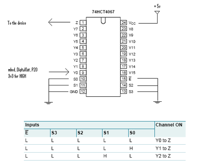
How to connect a DigitalOut to a device expecting min. 4 volt for an high

28 Dec 2010

Hi All,

I am using P20 as DigitalOut. My code is producing outputs 1 or 0 by using a particular data format. I attached a led to the output and it was blinking smoothly with a pattern I defined in the code.

So far so good. But, this was not my purpose of blinking a led. I have a device to consume this data. It has opto-coupled input and expecting minumum 4 volt input for an HIGH (1) value. Since mbed generates 3.3 volt for the HIGH (1), i can't get the device working. In the first place I thought it is a good idea to use LEVEL Converter from 3.3 volt to 5 volt and I used nMosfet BSS138. Before connecting the device to the leveler output I wanted to test it by the led I used for the P20 output. But, it didn't exhibit the same smooth blinking as the P20 pin output, it was continuesly ON (at least it appears so). 

I used voltmeter to meausure the output voltage and I saw that there is only 5 volt. It doesn't follow the signal level at all. (unfortunately, I don't have a scope to see real things)

Could you please put me on the right track and tell me what is going on and/or what should I do to provide proper signalling to the device.

Thanks a lot in advance.

Sener


28 Dec 2010

Use a dedicated level converter from 3v3 to 5v logic from TI. Search the forum for the subject.

You can use any HCT(even HC) IC buffer/inverter/gate with 5v supply and input to mbed.

Put a "simple" R-BaseNPN-CollectorOPTO-5v(emitter GND) and it's solved.

29 Dec 2010

I think you offer three different solutions for this and anyone of them should solve the problem.
If so, I've already applied a 3.3v > 5v level converter and didn't help. i don't know what was wrong with it. Perhaps, there must be something else to do additionaly!

I'll give a try to the HCT.

Thanks.

03 Jan 2011

After I had given a try to the BSS138 level converter, I've also used the circuit with 74HCT4067 below.

74hct4067_as_level_converter_for_an_mbed_digitalout

But, Unfortunately, this didn't also drive my device. When I connect a led to the ouput of the Z pin, it blinks correctly according to my data pattern. I measured the Z output was around 3v3 that doesn't also meet minimum 4 volt requirement of the device.

Any more suggestions?

Thanks,

Sener

03 Jan 2011

If you want tu use 4067 it is better to do it like this

connect mbed output to s0, y0 to GND and Y1 to 5v. When mbed output is high y1 is connected to z, when low y0 is routed to z.

Pay attention that a transfer gate like 4067 could not support more then 10-15mA so the output capability of mbed (40mA) is significantly reduced.

03 Jan 2011

The HCT4067 is an analog multiplexer. This means that the S0-S3 pins select which analog signal (Y0-Y15) is routed to Z. But in your case the input signal has only 3.3 volts, so the output signal cannot be more than that. Use something like a HCT245 or a LVC1T45 for conversion - they are designed for logic level conversion.

04 Jan 2011

Hendrik you should read more carefully my post. ;) On Z output you have 5v or 0v. Mbed is not connected to mux but to command pins. 

04 Jan 2011

user Not Important wrote:

Hendrik you should read more carefully my post. ;) On Z output you have 5v or 0v. Mbed is not connected to mux but to command pins.

Actually I was responding to Sener, no to you, trying to explain why his circuit doesn't work (but yours would). I should have stated that more clearly, sorry.


hli

07 Jan 2011

Hi all..

I would have posted a simple transistor switching circuit as a solution. (i.e. a transistor and a base resistor)

switching a 5v line to the device.

As I can PWM across a transistor, (they are fast enough). I thought this would be no problem.

Is there a reason thats not a good idea ?


(other than you have to find 5v from somewhere? and you only get 5v from mbed when connected to a USB)

16 Jan 2011

It has opto-coupled input and expecting minumum 4 volt input for an HIGH (1) value.

Have you considered useing an Opto-Coupler to driver their OptoCoupler?