input nR

13 Dec 2010

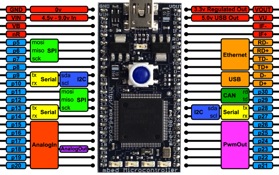
I inadvertently connected the +5V supply to the 'nR' pin  4- it seems to have stopped the Mbed working - the blue illuminated LED is extinguished - is the module recoverable please?

14 Dec 2010

The pin is connected directly to the MBED-IF01 chip (IF_NRESET_EXT line, pin46. Its tied to +3.3V through pullup.

Probably the input pin of the chip is damaged. A replacement is difficult, since it is a preprogrammed micro.

The only chance (without warranty and risk for other damages) is to shorten or decrease the value of R4 (10 kOhm). Could be also done externally by linking Vout (pin40) to nR (pin4). Good luck!

15 Dec 2010

Sorry the pin was on the development pcb

I am not sure which pin on the chip this corresponds to? (pin 4 nR). Does your response still stand please?

15 Dec 2010

Many thanks, Will try it tomorrow and let you know how things go.

15 Dec 2010

this is the schematic of the board, maybe you did not find yet. http://mbed.org/media/uploads/chris/mbed-005.1.pdf

16 Dec 2010

Stefan,

There is no 3.3V on prototype board pin 4. Is there a layout diagram for the board please? I did have a quick look but was unsuccessful. Thanks Dave

20 Dec 2010

Dave,

/media/uploads/smayr/wire.jpg

this is, what I meant by connecting the pin4 to pin40.

Did you power the board through the USB cable?

21 Dec 2010 . Edited: 14 Jan 2011

No I connected a +5V PSU to nR.

Your diagram above shows the right demo PCB pin on the left (nR), but it went straight to the +5V supply (3A capable). Which also went to Vin (pin 2 on PCB)

Is there a layout showing components and circut for the prototype board please?

14 Jan 2011

No I connected a +5V PSU to nR.

Your diagram above shows the right demo PCB pin on the left (nR), but it went straight to the +5V supply (3A capable). Which also went to Vin (pin 2 on PCB)

Is there a layout showing components and circut for the prototype board please?

15 Jan 2011
15 Jan 2011 . Edited: 31 Jan 2011

Many thanks, I can follow the schematic but the component numbers is not on the PCB and I am unable to trace the tracks (under components and multi layer), if there is a layout diagram of the PCB it would help identify the components - it seems that the regulator may not be providing 3.3V to the 'problem' pin. Thanks, Dave S

Should I interpret no feedback as no info existis please?

31 Jan 2011

Should I interpret no feedback as no info existis please?