Controlling ADC with SPI

16 May 2011

Hello,

Above all I would like to apologize for the quality of my English, I'm french.

I'm a beginner and I am currently about to try a analog-to-digital converter with my mbed. It's the MAX11110, you can find technical documentation here :

http://datasheets.maxim-ic.com/en/ds/MAX11102-MAX11117.pdf

It consists of 6 pins that I connected this way in mbed :

/media/uploads/captorsaw/cablage.png

The CS pin is from what I understood to activation of the conversion request. When one wants to have a measure passed this pin to 0, the conversion occurs and is reset to 1.

To view on oscilloscope the data bus DOUT, ​​I made ​​this little program. Alas, I see nothing in DOUT and I can't visualize the clock, I have a similar signal on the clock and CS. It's weird.

Thank you for your help !

Rémy

16 May 2011

#include "mbed.h"

Serial pc(USBTX, USBRX);
SPISlave can(p5, p6, p7, p8);
DigitalOut cs(p9);

int main() {

   can.format(10, 0);
   can.frequency(1000000);

   while(1){
        cs=1;
        wait_us(2);
        cs=0;
        wait_us(16);
    }
}
16 May 2011

Some suggested changes:

1.Use SPI, not SPISlave, in the library invocation. Like this:

SPI can(NC, p6, p7);   // MOSI is not connected

2. Wire mbed p9 ("cs") to the MAX11110 pin 6 ("CS/").

3. Set up the SPI controller for 16-bit transfers (see Figure 5 of the data sheet). Like this:

can.format(16,0);

Hope that helps.

16 May 2011
23 May 2011

Thank you for your helping.

But, I've still some problems. I've used this code :

#include "mbed.h"

Serial pc(USBTX, USBRX);
SPI can(NC, p6, p7);
DigitalOut cs(p9);


int main() {

    can.format(16, 0);
    can.frequency(1000000);
   
    pc.printf("Starting ADC interaction\n");
   
    while(1){

        cs=0;
        wait_us(16);
        
        cs=1;
        wait_us(2);
        
    }

}

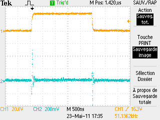
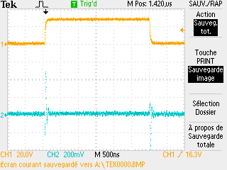
And I get this, on the oscilloscope, yellow signal is cs and blue signal is data :
/media/uploads/captorsaw/tek0001.png

/media/uploads/captorsaw/tek0002.png

As you can see, the time where the cs is at 1 varies between 2 and 3 us. I don't understand why ? And, there are nothing in data and in clock.

So, I've tried this code, in using the SPIHalfDuplex function :

#include "mbed.h"

Serial pc(USBTX, USBRX);
SPIHalfDuplex can(NC, p6, p7);
DigitalOut cs(p9);


int main() {

    can.format(16, 0);
    can.frequency(1000000);
   
    pc.printf("Starting ADC interaction\n");
   
    while(1){

        cs=0;
        
        int respone = can.write(0xAA);
        pc.printf("Reponse : %u", respone);
        
        wait_us(16);
        
        cs=1;
        wait_us(2);
        
    }

}

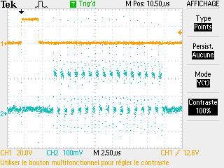
And I get this on the oscilloscope (cs, data) :
/media/uploads/captorsaw/tek0006.png

On my PC, I get : "Reponse : 4294967295". But this value doesn't change if I vary the voltage to be converted. And I don't understand why the value is 2^32 - 1. Also, the clock is still not visible.

Thank you for your help.

23 May 2011

Rémy Jeannot wrote:

So, I've tried this code, in using the SPIHalfDuplex function ... On my PC, I get : "Reponse : 4294967295". But this value doesn't change if I vary the voltage to be converted. And I don't understand why the value is 2^32 - 1. Also, the clock is still not visible.

It seems that you are getting close. Some comments:

1. You don't need SPIHalfDuplex; the normal SPI function should work.

2. Something is wrong with the "data" signal. It is only 200mV in amplitude in the scope photo. Also, the pattern looks like the expected clock signal, not a valid data sequence. We seem to be seeing cross-coupled noise from the clock line. You should be seeing these 16 pulses, with full 3.3V amplitude, on pin 4 of the MAX11110 and pin 7 of the mbed. Is it possible there is a wiring problem?

3. You are getting all ones for input data. This may be due to a timing problem (the "half duplex" configuration, for example) or a wiring issue. Here's an experiment: disconnect the wire from the MAX11110 pin 5 that goes to mbed pin 6. Then connect mbed pin 6 to ground. Now run your test and you should get "Response : 0", since this will force all the MISO data to zero.