Using low cost STM32F103C8T6 boards with mbed.

24 Nov 2016

Hello,
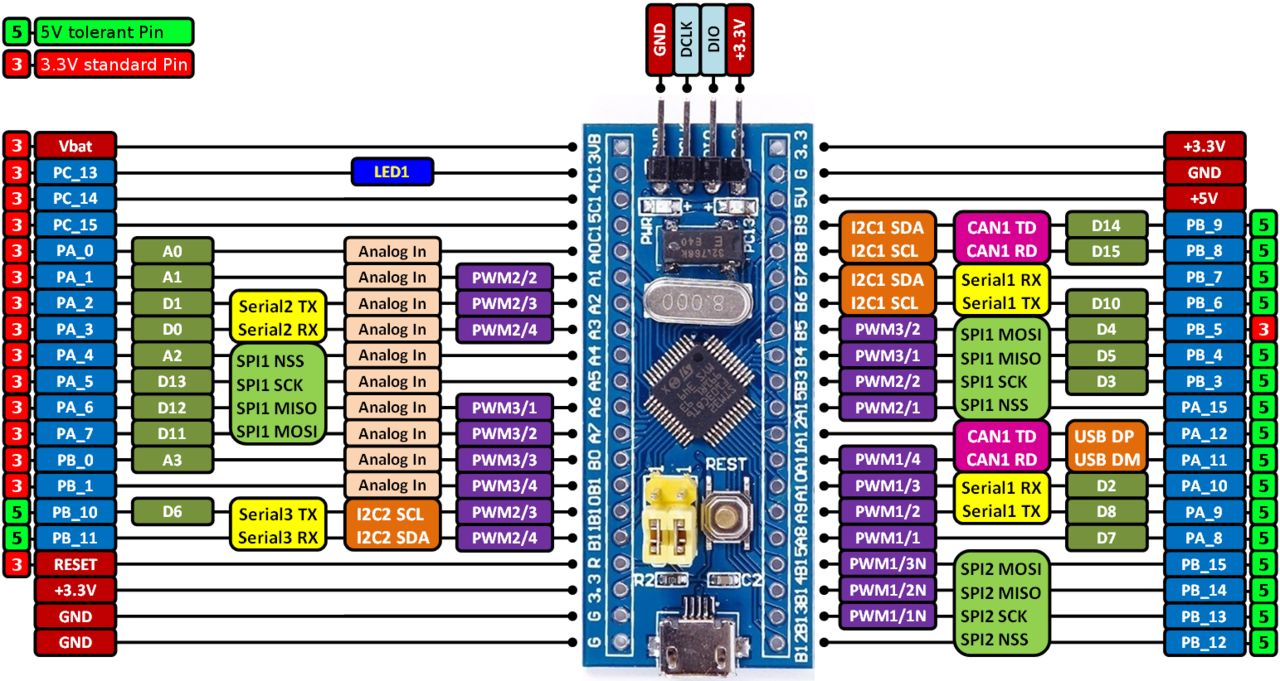
STM32F103C8T6 boards provide an affordable (less than $3 on eBay) and flexible way for users to try out new ideas and build prototypes. /media/uploads/hudakz/stm32f103c8t6_pinout_voltage01.png

You can straight away create programs for such boards using the mbed on-line compiler and program them with the ST-Link programmer (available on any ST NUCLEO board) by utilizing the NUCLEO virtual disk drag and drop technique.
For more information have a look at the STM32F103C8T6 Wiki Page.
Your feedback is welcome.

23 Aug 2016

I did not know the cost was so low. Some are under $3 shipping included.

Would you have a link to better hardware documentation? Your colored pinout diagram is almost enough.

One question I have is the crystal. All the eBay sellers seem to have copy and pasted the same specs and say "crystal 4-16 MHz". Does this mean it might be anywhere between 4 MHz and 16 MHz. I notice the unit in your photo is stopped "8 Mhz" So, does the ARM always run at 72 MHz All the cut and pasted specs read "72 MHz work frequency".

Those yellow jumpers might do some standard function as I see them on other boards

11 Sep 2016

Hi I'm new programming SMT, 32 bit, I would like to know which are digital pins on the board. gretting :)

16 Oct 2016

Hello Chris,
There is a schematic available on the STM32F103C8T6 Wiki page and also a link to the chip's datasheet. The board is equipped with a 8 MHz crystal and runs at 72 MHz CPU frequency. The RTC is using a 32 768 Hz crystal.
The yellow jumpers are used for configuring the boot mode selection pins to program the board over the STM32 USART system memory bootloader. For more details have a look at the Application Note 2606.
Best regards, Zoltan.

16 Oct 2016

Hello Mauricio,
You can create a DigitalIn, DigitalOut, DigitalInOut or InterruptIn on any of the following pins:

  • PA_0, PA_1, PA_2, PA_3, PA_4, PA_5, PA_6, PA_7, PA_8, PA_9, PA_10, PA_11, PA_12, PA_15,
  • PB_0, PB_1, PB_3, PB_4, PB_5, PB_6, PB_7, PB_8, PB_9, PB_10, PB_11, PB_12, PB_13, PB_14, PB_15,
  • PC_13, PC_14, PC_15.

NOTE: PC_13 is connected to the on-board LED.

For more info on mbed's API have a look at the Handbook - Homepage.
Best regards, Zoltan.

28 Dec 2016

This is cool, i will give it a try one day. Thanks for all the documentation

17 Aug 2017

great job! Thank U!

15 Feb 2018

Well, I just went through 4 of these. The average life span was 48 hrs. Maybe I got a bad batch.....ordered 4 more. Time will tell.

You don't need to change jumpers when using a programmer. You can upload a bin file via external serial port with jumpers selected.

Apply power via the 5v pin or usb port. You would have to remove the regulator to be able to apply power directly to any of the 3v pins.

While they worked, they worked well with mbed or arduino (you don't need a boot loader). My interest was with mbed.

25 Feb 2018

Followup: I received my mcu's. I uploaded the mbed blink and it barely lasted 48hrs. It's dead in the water.

I suspect they probably make these with rejected chips or a static ladened environment.

Either way, it looks like I will be sticking with my actual ST discovery boards. Buy once / use many is much cheaper then buy many / use once.

09 Apr 2018

The board is nice. Low cost and if you're lucky, you'll get 128kb of flash. Testing using mbed and it's working. The output bin file is big. I was testing CAN bus using this library

Import programCAN_Hello

Using CAN bus with (not just NUCLEO) mbed boards

using SN65HVD230 transceiver is working but the micro USB power should connected to USB Computer. When i plugged into USB Charger or using external V5 pin, it not working. The sender send 3 transmission, the rest is failure. And the receiver can't get the message anything.

20 Apr 2018

It's due to the design of USB chargers where the USB_DP and USB_DM pins are connected one another inside the USB connector (like in this case). When such USB charger is used, since the USB_DP and USB_DM pins are at the same time connected to the PA_11, PA_12 pins, the CAN RD and CAN TD pins become connected one another over the USB charger and the CAN peripheral fails to operate. To avoid such short circuits try to connect the CAN peripheral to the PB_8, PB_9 pins and modify the program accordingly.

CAN   can(PB_8, PB_9);  // CAN Rx pin name, CAN Tx pin name
02 Jul 2018

Peter Carter wrote:

Well, I just went through 4 of these. The average life span was 48 hrs. Maybe I got a bad batch.....ordered 4 more. Time will tell.

You don't need to change jumpers when using a programmer. You can upload a bin file via external serial port with jumpers selected.

Apply power via the 5v pin or usb port. You would have to remove the regulator to be able to apply power directly to any of the 3v pins.

While they worked, they worked well with mbed or arduino (you don't need a boot loader). My interest was with mbed.

I have had several of these that got into a state where they could no longer be programmed. Go into STM32 ST-Link utility and do " erase chip", hold reset down, and then hit enter, then quickly release reset. If you do this right you will see the chip being erased and then it will accept new programs.

- Bert

02 Jul 2018

I have since purchased a usb current/voltage meter.. My issues were ore likely over voltage as my external usb hubs were much higher than ones on my computer and also more susceptible to fluctuations due to loading. My hubs may also behave like Zoltan suggested.

My better fabricated boards tend not to suffer from these issues. I have just gone back to using those.

06 Dec 2018

As per my observation this is right that you need not to change jumpers when using a programmer. You can upload a bin file via external serial port with jumpers selected. Also apply power via the 5v pin or usb port. You would have to remove the regulator to be able to apply power directly to any of the 3v pins.

https://percentagescalculator.com/

13 Dec 2018

Sorry !would you please help me... I have one Broad STM32F103C8T6 but crystal is 12Mhz .How can i change the setting clock if i import stm32f103c8t6.h libary ( Made by Zoltan Hudak )? Thanks!

29 Dec 2018

When using a 12MHz external crystal try to modify the assignment of RCC_OscInitStruct.PLL.PLLMUL in SysClockConf.cpp file as follows:

SysClockConf.cpp

// ...

void HSE_SystemClock_Config(void) {

    // ...

    //RCC_OscInitStruct.PLL.PLLMUL = RCC_PLL_MUL9;  // when using 8MHz external crystal
    RCC_OscInitStruct.PLL.PLLMUL = RCC_PLL_MUL6;  // when using 12MHz external crystal

    // ...

}
04 Jan 2019

Thank you @Zoltan Hudak ! I did try ,but it did not work! i did change Xtal 8Mhz and it worked well,