Hello friends.
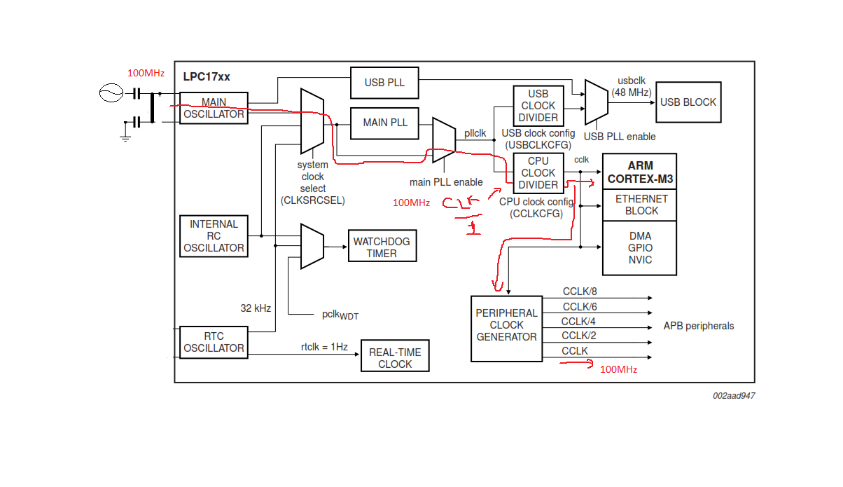
Initially I was thinking of doing such a system like Figure 1.
(Ps: sorry improvised scheme, but it was the quickest way to facilitate understanding)

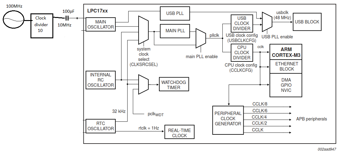
I check datasheet again and saw that the limits for the external clock system range from 1MHz to 25MHz. Ok, now I have a specification. Knowing that I thought to divide the clock of 100MHz for 10, just getting a 10MHz clock referenced in the 100MHz crystal. But I do not know if that frequency would be compatible with the APIs of mbed. In this scheme:

I know the mbed uses an external 12MHz crystal and its APIs configure the (PLL) to work on that frequency and generate an internal clock of about 96MHz. But I still have a second option, as suggested also, I own a DDS AD9912, I can configure it to generate a fixed 12MHz signal to be delivered to the mbed clock system and referenced in the 100MHz crystal. This system is what strikes me the most inviting.
What do you think?
This is my crystal:
http://www.wenzel.com/wp-content/parts/501-16843.pdf
Thank you
Hi, companions developers. I have some mbed's and I made my own pcb too, now a want make tests with precise external clock sources, I have a oscillator like this:
http://www.wenzel.com/model/vhf-uln/
But, the output of the oscillator is senoidal and has 100MHz, I would like know, if is possible use this signal direct with a100pF coupled capacitor on pin 22 (LPC1768) in one of my customized PCB's. I need devide this signal to approximate 12MHz, so I can use mbed's API's or 100MHz it's a clock frequency possible to run the microcontroller? I need pass my clock signal in a schmitt trigger circuit to entry with a square wave signal in XTAL 1 pin same with a frequency of 100MHz, but now square shaped?
Any help is aprecieted.
Any help is welcome.
Thanks.