External clock sources

17 Jun 2015

Hi, companions developers. I have some mbed's and I made my own pcb too, now a want make tests with precise external clock sources, I have a oscillator like this:

http://www.wenzel.com/model/vhf-uln/

But, the output of the oscillator is senoidal and has 100MHz, I would like know, if is possible use this signal direct with a100pF coupled capacitor on pin 22 (LPC1768) in one of my customized PCB's. I need devide this signal to approximate 12MHz, so I can use mbed's API's or 100MHz it's a clock frequency possible to run the microcontroller? I need pass my clock signal in a schmitt trigger circuit to entry with a square wave signal in XTAL 1 pin same with a frequency of 100MHz, but now square shaped?

Any help is aprecieted.

Any help is welcome.

Thanks.

19 Jun 2015

You would probably want a DDS http://www.analog.com/en/products/clock-and-timing/direct-digital-synthesis.html Some MCU clock input might accept sine wave, check datasheet, or use comparitor.

19 Jun 2015

The datasheet for the lpc1768 says that Xtal1 (input) must be between 1MHz and 25MHz. You should use 12MHz for direct compatibility with the mbed libs. Using other frequencies means that you have to modify some settings.

The input voltage to the on-chip oscillators is limited to 1.8 V. If the oscillator is driven by a clock in slave mode, it is recommended that the input be coupled through a capacitor with Ci = 100 pF. To limit the input voltage to the specified range, choose an additional capacitor to ground Cg which attenuates the input voltage by a factor Ci/(Ci + Cg). In slave mode, a minimum of 200 mV(RMS) is needed. In slave mode the input clock signal should be coupled by means of a capacitor of 100 pF (Figure 35), with an amplitude between 200 mV(RMS) and 1000 mV(RMS). This corresponds to a square wave signal with a signal swing of between 280 mV and 1.4 V.

The XTALOUT pin in this configuration can be left unconnected.

19 Jun 2015

Hello friends. Initially I was thinking of doing such a system like Figure 1. (Ps: sorry improvised scheme, but it was the quickest way to facilitate understanding)
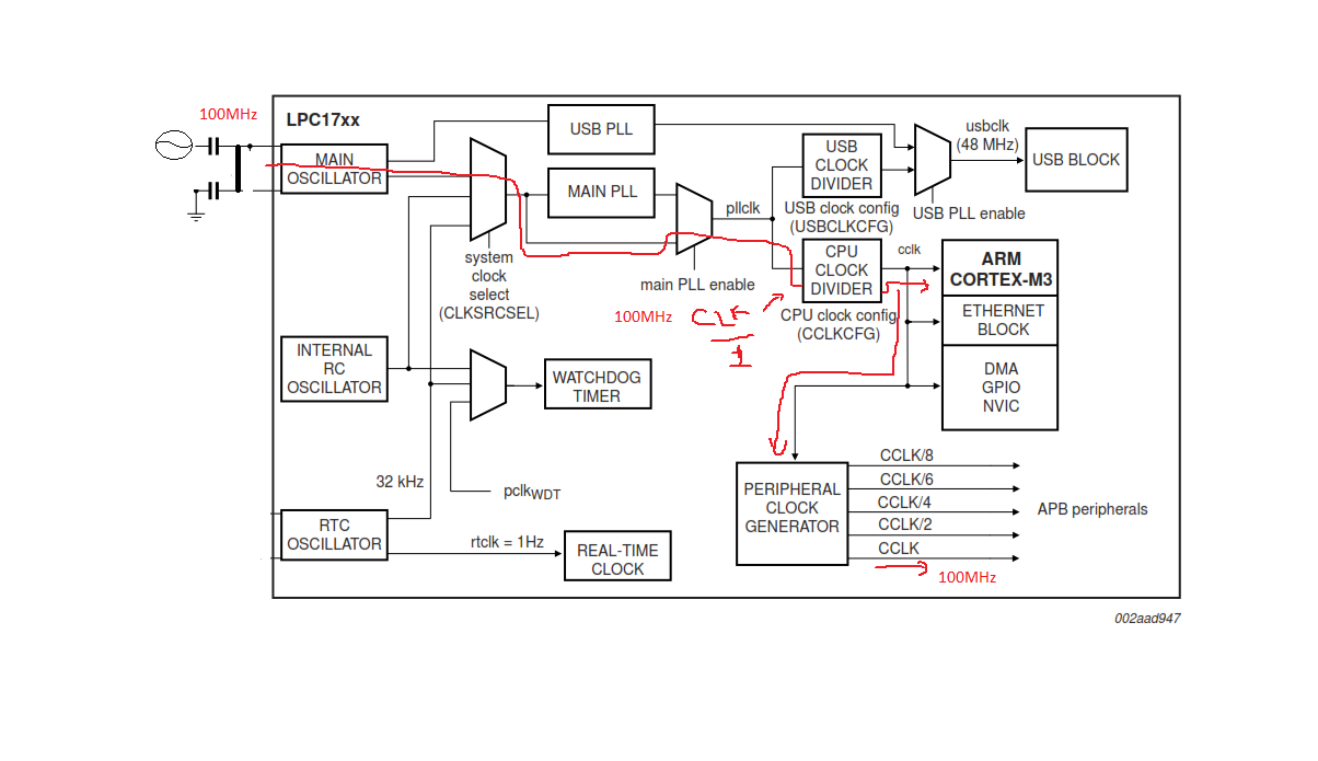
/media/uploads/Rodrigo_Che/clock_1.png

I check datasheet again and saw that the limits for the external clock system range from 1MHz to 25MHz. Ok, now I have a specification. Knowing that I thought to divide the clock of 100MHz for 10, just getting a 10MHz clock referenced in the 100MHz crystal. But I do not know if that frequency would be compatible with the APIs of mbed. In this scheme:
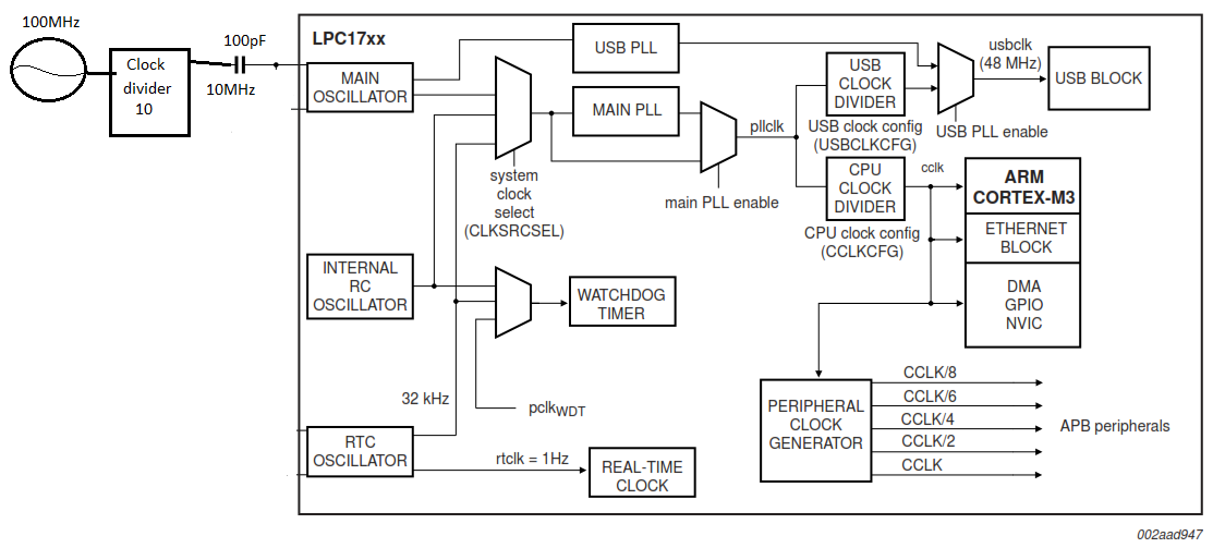
/media/uploads/Rodrigo_Che/clock_2.png

I know the mbed uses an external 12MHz crystal and its APIs configure the (PLL) to work on that frequency and generate an internal clock of about 96MHz. But I still have a second option, as suggested also, I own a DDS AD9912, I can configure it to generate a fixed 12MHz signal to be delivered to the mbed clock system and referenced in the 100MHz crystal. This system is what strikes me the most inviting.

What do you think?

This is my crystal: http://www.wenzel.com/wp-content/parts/501-16843.pdf

Thank you

20 Jun 2015

I dont really see why you want to use a very accurate external clock and then DDS it to 12 MHz and then use internal PLLs on top of that to generate the SystemCoreclock. There will definitely be some noise and jitter in the resulting frequency. Anyhow, you can probably do without the DDS step and use the LPC1768 PLL directly to generate a systemclock of 100MHz or so from your 10 MHz. Note that the internal clock was set at 96 MHz to easily derive the 48MHz USB clock. You dont need that when you dont plan to use the USB. When you want to change the PLL settings because of a different external xtal it is best to import the mbed source code in your project and change the PLL setup in the initialisation part of that code.

Depending on your objectives, it may also be possible to use the internally generated clocksignal in your external system. The clock can be presented as output on a pin. Internal counters/timers could also use an external clocksource.

22 Jun 2015

I understand, I have clock dividers that generate 1/4 of frequency, in other words, without using DDS I can get a clock of 25 MHz directly on 100MHz crystal. This resolve my problem number one, now, I don't know if LPC1768 works with senoidal signal or only square wave, in datasheet seems that the senoidal is possible, but this I can solve easily. how do I change the frequency of SystemCoreClock on mbed source code properly? I am very grateful for your the help.

22 Jun 2015

This is my scheme: /media/uploads/Rodrigo_Che/sem_t-tulo.png