USB device stack
Introduction
A functional Mbed OS USB device consists an implementation of USBPhy, the USBDevice stack and a USB component code:
- USBPhy provides raw access to USB in the role of a USB Device.
- USBDevice is the core of Mbed OS's USB stack and is responsible for state management and synchronization.
- USB component is code that inherits from USBDevice and provides the desired USB interfaces.
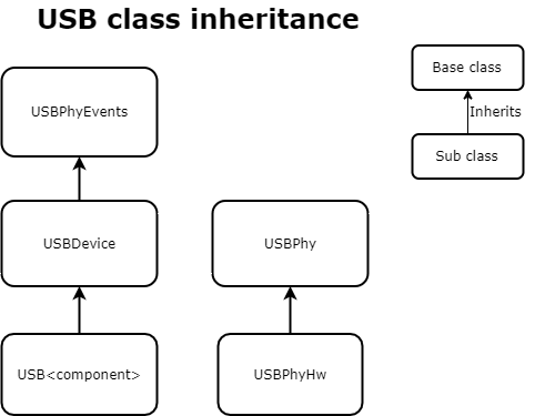
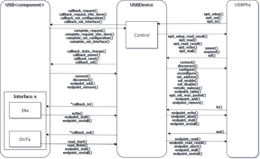
You can see the interaction of these three components in this diagram:
Synchronization
The class USBDevice is interrupt-safe. It uses a critical section to provide thread- and interrupt-safe locking. USB components inheriting from USBDevice can use this lock, but it is not required.
The recommended model for synchronizing a USB component is to wrap code requiring synchronization in a call to USBDevice::lock and USBDevice::unlock. Functions or callbacks already synchronized by a caller at a higher level should document this locking requirement by calling USBDevice::assert_locked in the first line of the function or callback.
Code requiring locking:
void USBComponent::do_something()
{
    lock();

    // Do do something

    unlock();
}
Code that expects a caller at a higher level to hold the lock:
void USBComponent::do_something_internal()
{
    assert_locked();

    // Do do something
}
USB device state
USB defines five separate states of a device: Attached, Powered, Default, Address and Configured. Each state adds functionality. The Attached state has the least functionality, and the Configured state has the most functionality.
| State | Functionality |
|---|---|
| Attached | Power events |
| Powered | Reset events |
| Default | Control endpoint 0 active |
| Address | No new functionality |
| Configured | All enabled endpoints are functional |
Random power loss can cause the USB device to lose functionality. When leaving or outside of the Configured state, USBDevice ignores writes to and reads from all endpoints other than endpoint 0.
USB component callbacks
All callbacks USBDevice sends to its children are prefixed with callback_*. USBDevice calls these callbacks with the USB lock held. One notable callback is callback_state_change, which USB components can use generically to handle leaving the Configured state. The USB stack automatically exits the Configured state on disconnect, power loss or USB reset.
Control request state machine
There are four callbacks that the USB control state machine sends. When USBDevice calls these callbacks, the USB component must return a result to continue the control state machine. The USB component does not need to return the result immediately, which gives it time to process the request. Note that the USB component must always send the response, regardless of any USB device state changes.
Table of control callbacks and the required response:
| Callback | Response |
|---|---|
| callback_request(setup_packet) | complete_request(result, data, size) |
| callback_request_xfer_done(setup_packet, aborted) | complete_request_xfer_done(result) |
| callback_set_configuration(configuration) | complete_set_configuration(result) |
| callback_set_interface(interface, alternate) | complete_set_interface(result) |
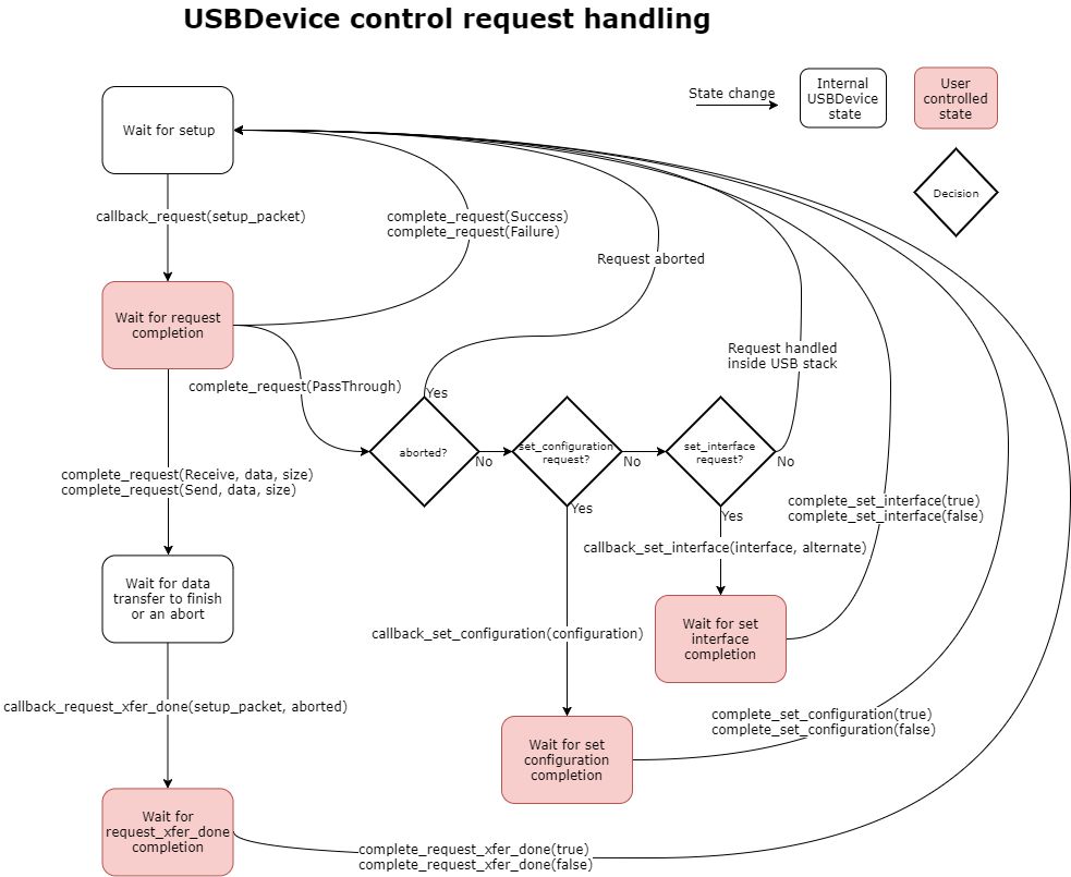
The USB stack guarantees the setup packet passed to callback_request and callback_request_xfer_done remains valid and unchanged up to the point the USB component completes the request with complete_request and complete_request_xfer_done. Additionally, when the USB component calls complete_request with the value Receive or Send, the USB stack guarantees that callback_request_xfer_done is called. If the USB component calls complete_request with a buffer and size, that buffer must remain valid and unchanged until USBDevice calls the function callback_request_xfer_done.
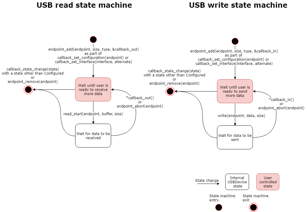
IN and OUT state machine for endpoints
A USB component adds and removes endpoints as part of callback_set_configuration and callback_set_interface to set up the corresponding interface or configuration. Additionally, USBDevice automatically removes all added endpoints if the device leaves the Configured state.
When a USB component adds an endpoint, you can either write to it with write or read from it by calling read_start and read_finish. The buffers passed to write or read_start must remain unchanged until the operation is complete, indicated by USBDevice calling the endpoint callback, or you abort the operation with endpoint_abort. Note that for write, the buffer size must not exceed the maximum packet size for the given endpoint. For read_start, the buffer must be at least the maximum packet size.
Below is a diagram showing the typical state machine for read (OUT) and write (IN) transfers.
Endpoint configuration
To ensure a USB component runs on all supported devices, the USB component must select the configuration descriptor's endpoints based on the current device. This is because endpoint number and endpoint functionality can differ by device. A USB component can determine the features of USBPhy by examining its endpoint table.
To simplify the process of selecting endpoints, use the EndpointResolver class. A USB component constructs the class with an endpoint table. The USB component can then call the class to find an endpoint of the given type and size. After the component finds all required endpoints, it can call the function EndpointResolver::valid() to determine whether this device supports this configuration. Below is an example of this:
EndpointResolver resolver(endpoint_table());
resolver.endpoint_ctrl(CDC_MAX_PACKET_SIZE);
bulk_in = resolver.endpoint_in(USB_EP_TYPE_BULK, CDC_MAX_PACKET_SIZE);
bulk_out = resolver.endpoint_out(USB_EP_TYPE_BULK, CDC_MAX_PACKET_SIZE);
int_in = resolver.endpoint_in(USB_EP_TYPE_INT, CDC_MAX_PACKET_SIZE);
MBED_ASSERT(resolver.valid());