iRobot Create Robot or a Roomba
The Create is basically a low-cost Roomba without the vac parts designed for educational users. The cost is reasonable since it benefits from the mass production of the Roomba
Hello World

Library
Datasheet
http://www.irobot.com/filelibrary/create/Create%20Manual_Final.pdfNotes

This is a simple project that shows how to interface mbed to control the iRobot Create robot. The Create is basically a low-cost Roomba without the vac parts designed for educational users. The cost is reasonable since it benefits from the mass production setup of the Roomba for the consumer market. iRobot was founded by a faculty member and two students from MIT's Artificial Intelligence Lab. The Create comes assembled and educational discounts are available for schools. The Create has an internal microcontroller with firmware, a serial port, two reversible drive motors with feedback, and thirty internal sensors.

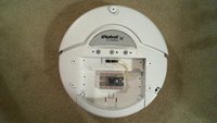
The iRobot Create with the cover removed

A closer view of the Create control boards
In the image above, the processor is hidden underneath the ribbon cable in the center on a vertically mounted PCB. Quite a lot of connectors and cabling inside going to all of the sensors and motors. It is really nice that it comes assembled. It saves a lot of time to have an assembled robot especially when you need a dozen or more of them for a class of students or a large event.
Over the serial port, you can send motor commands and read back sensor packets. The Create comes with a custom serial cable, but it uses RS-232 signal levels so that it can plug into a PC serial port. To control it using mbed, you need to connect to the serial port with TTL levels and provide power for the mbed module.
mbed Hardware Interface
Inside the Create robot cargo area is a DB25 connector that has all of these connections. With only four jumper wires you can connect everything needed. This is not a standard pinout for a serial connector, all of the pins have special uses for the Create. Pin assignments can be found in the Create User Manual.

Here are the four connections to the Create:
| mbed | Create DB25 Pin | Description |
|---|---|---|
| p9 | 1 - RXD (0 – 5V) | Serial input to iRobot Create |
| p10 | 2 - TXD (0 – 5V) | Serial output from iRobot Create |
| Vin | 8 - Switched 5V | Provides a regulated 5V supply (low current) |
| GND | 16 - GND | iRobot Create battery ground |
In the demo setup seen above, a small breadboard with double sided tape was used to hold the mbed module in place. Jumper wires from the breadboard were inserted into the DB25 connector socket. Reliable connections are a good idea on anything that moves and shakes like a robot. If your jumper wires will not fit, get a male DB25 connector with solder pins and solder all of the connections. There is also a Bluetooth module available for the Create that plugs directly into the DB25 connector.
Alternative Serial Cable Interface
If you have an RS-232 level shifter breakout board for your mbed, as an alternative you can use the serial cable supplied with the Create, and run the robot demo code on a tether without having to mount and power the mbed on the robot. The Create serial cable has an LED display during serial data transfers. This cable plugs into another small Mini-DIN 7 connector near the outside edge of the robot. If the robot does not move while running the demo code and the LEDs do not flash, you may also need a null modem adapter or cable (i.e., swaps TX and RX) and even a gender changer if the cables will not all plug together. The serial cable may be useful, but for initial testing only. The robot can only move a few feet before you will run out of cable. When using the serial cable, you will also need to turn on the robot first, and then reset the mbed.

The Create's custom serial cable seen above contains an RS-232 level shifter and LED status display

Here is a serial cable setup using mbed that will control the Create or Roomba. A Sparkfun RS-232 SMD adapter, a DB9 null modem (orange stripe above), and a MM DB9 gender changer (yellow stripe above) were required. The mbed still needs power from the USB cable in this setup.
| mbed | Sparkfun RS232 SMD adapter |
|---|---|
| 3.3V | Vcc |
| Gnd | Gnd |
| P9 - TX | RX |
| P10- RX | TX |
mbed Roomba Hack
All Roombas made since October 2005 also respond to a subset of the same basic serial command set. So as an alternative to a Create, you can use an old Roomba, but with the subset of commands used on Roomba. A similar cable can also be made for a Roomba as described in the Hacking Roomba book or you can use a Create serial cable. Sparkfun also has a USB RooStick and a Bluetooth RooTooth. iRobot also has a new Create USB cable. The 5V serial connections are also available directly from the Mini-DIN 7 connector on the Roomba, but not a 5V regulated supply for the mbed module. The unregulated 18V battery voltage is on the connector instead. Sparkfun also has a special Roomba cable that will fit the mini-DIN 7 and you could use it to access the TTL serial pins. So far, no one makes a mini-DIN 7 breakout board, so you would probably need to cut the cable. The battery output on the mini-DIN 7 connector is low current only. The Create was actually developed in response to all of the Roomba hacking activity by robotics hobbyists.

A used Roomba controlled by mbed using the Create serial cable
mbed Create Demo Code
The demo code sends out serial commands to the Create. Serial commands can be found in the Create Open Interface Manual. Sensor values are also reported back over the serial port, but are not used in the short demo code. Here is a short video of the demo code running on the Create:
The demo code is shown below. Basically it waits for the Create to power up, sets the baud rate to 57600, and then starts sending a sequence of commands over the serial port with time delays between commands. The serial commands are sent in a binary format and are typically not printable ASCII characters. For robot safety, a start command must be sent before it will respond to motor commands. In normal safe mode, the robot motors will not run unless it is placed on the floor. IR cliff sensors on the bottom are designed to keep it from running off steps.
Create_Demo
#include "mbed.h"

Serial device(p9, p10);  // tx, rx

// Definitions of iRobot Create OpenInterface Command Numbers
// See the Create OpenInterface manual for a complete list


//                 Create Command              // Arguments
const char         Start = 128;
const char         SafeMode = 131;
const char         FullMode = 132;
const char         Drive = 137;                // 4:   [Vel. Hi] [Vel Low] [Rad. Hi] [Rad. Low]
const char         DriveDirect = 145;          // 4:   [Right Hi] [Right Low] [Left Hi] [Left Low]
const char         Demo = 136;                 // 2:    Run Demo x
const char         Sensors = 142;              // 1:    Sensor Packet ID
const char         CoverandDock = 143;         // 1:    Return to Charger
const char         SensorStream = 148;               // x+1: [# of packets requested] IDs of requested packets to stream
const char         QueryList = 149;            // x+1: [# of packets requested] IDs of requested packets to stream
const char         StreamPause = 150;          // 1:    0 = stop stream, 1 = start stream
const char         PlaySong = 141;
const char         Song = 140;
                /* iRobot Create Sensor IDs */
const char         BumpsandDrops = 7;
const char         Distance = 19;
const char         Angle = 20;

int speed_left =  200;
int speed_right = 200;
void start();
void forward();
void reverse();
void left();
void right();
void stop();
void playsong();
void charger();

// Demo to move around using basic commands
int main() {
// wait for Create to power up to accept serial commands
    wait(5);
// set baud rate for Create factory default
    device.baud(57600);
// Start command mode and select sensor data to send back
    start();
    wait(.5);
// Move around with motor commands
    forward();
    wait(.5);
    stop();
    wait(.1);
    reverse();
    wait(.5);
    left();
    wait(1);
    stop();
    wait(.1);
    right();
    wait(1);
    stop();
    wait(.5);
// Play a song
    playsong();
    wait(10);
// Search for battery charger IR beacon
    charger();
}


// Start  - send start and safe mode, start streaming sensor data
void start() {
   // device.printf("%c%c", Start, SafeMode);
    device.putc(Start);
    device.putc(SafeMode);
    wait(.5);
  //  device.printf("%c%c%c", SensorStream, char(1), BumpsandDrops);
    device.putc(SensorStream);
    device.putc(1);
    device.putc(BumpsandDrops);
    wait(.5);
}
// Stop  - turn off drive motors
void stop() {
    device.printf("%c%c%c%c%c", DriveDirect, char(0),  char(0),  char(0),  char(0));
}
// Forward  - turn on drive motors
void forward() {
    device.printf("%c%c%c%c%c", DriveDirect, char((speed_right>>8)&0xFF),  char(speed_right&0xFF),
    char((speed_left>>8)&0xFF),  char(speed_left&0xFF));

}
// Reverse - reverse drive motors
void reverse() {
    device.printf("%c%c%c%c%c", DriveDirect, char(((-speed_right)>>8)&0xFF),  char((-speed_right)&0xFF),
    char(((-speed_left)>>8)&0xFF),  char((-speed_left)&0xFF));

}
// Left - drive motors set to rotate to left
void left() {
    device.printf("%c%c%c%c%c", DriveDirect, char((speed_right>>8)&0xFF),  char(speed_right&0xFF),
    char(((-speed_left)>>8)&0xFF),  char((-speed_left)&0xFF));
}
// Right - drive motors set to rotate to right
void right() {
    device.printf("%c%c%c%c%c", DriveDirect, char(((-speed_right)>>8)&0xFF),  char((-speed_right)&0xFF),
    char((speed_left>>8)&0xFF),  char(speed_left&0xFF));

}
// Charger - search and return to charger using IR beacons (if found)
void charger() {
    device.printf("%c%c", Demo, char(1));
}
// Play Song  - define and play a song
void playsong() { // Send out notes & duration to define song and then play song

    device.printf("%c%c%c%c%c%c%c%c%c%c%c%c%c%c%c%c%c%c%c%c%c%c%c%c%c%c%c%c%c%c%c%c%c%c%c",
                  Song, char(0), char(16), char(91), char(24), char(89), char(12), char(87), char(36), char(87),
                  char(24), char(89), char(12), char(91), char(24), char(91), char(12), char(91), char(12), char(89),
                  char(12),char(87), char(12), char(89), char(12), char(91), char(12), char(89), char(12), char(87),
                  char(24), char(86), char(12), char(87), char(48));

    wait(.2);
    device.printf("%c%c", PlaySong, char(0));
}
mbed Roomba Demo Code
This version is the same basic demo, but it uses only the serial commands supported on the Roomba.
Roomba_Demo
#include "mbed.h"

Serial device(p9, p10);  // tx, rx

// Definitions of iRobot Roomba SCI Command Numbers
// See the Roomba SCI manual for a complete list


//                 Create Command              // Arguments
const char         Start = 128;
const char         Control = 130;
const char         FullMode = 132;
const char         Drive = 137;                // 4:   [Vel. Hi] [Vel Low] [Rad. Hi] [Rad. Low]
const char         Sensors = 142;              // 1:    Sensor Packet ID
const char         CoverandDock = 143;         // 0:    Return to Charger
const char         Clean = 135;                 // 0:    Start Cleaning
const char         PlaySong = 141;
const char         Song = 140;
                /* iRobot Roomba Sensor IDs */
const char         BumpsandDrops = 1;

int speed =  400;
int radius = 0x8000;
void start();
void forward();
void reverse();
void left();
void right();
void stop();
void playsong();
void charger();

// Demo to move around using basic commands
int main() {
// wait for Roomba to power up to accept serial commands
    wait(5);
// set baud rate for Roomba factory default
    device.baud(57600);
// Start command mode and select sensor data to send back
    start();
    wait(.5);
// Send commands to move around
    forward();
    wait(.5);
    stop();
    wait(.1);
    reverse();
    wait(.5);
    left();
    wait(1);
    stop();
    wait(.1);
    right();
    wait(1);
    stop();
    wait(.5);
// Play a song
    playsong();
    wait(10);
// Search for battery charger IR beacon
    charger();
}


// Start  - send start and safe mode, start streaming sensor data
void start() {
   // device.printf("%c%c", Start, SafeMode);
    device.putc(Start);
    wait(.1);
    device.putc(Control);
    wait(.5);
  //  device.printf("%c%c", SensorStream, char(1));
    device.putc(Sensors);
    device.putc(BumpsandDrops);
    wait(.5);
}
// Stop  - turn off drive motors
void stop() {
    device.printf("%c%c%c%c%c", Drive, char(0),  char(0),  char(0),  char(0));
}
// Forward  - turn on drive motors
void forward() {
    device.printf("%c%c%c%c%c", Drive, char((speed>>8)&0xFF),  char(speed&0xFF),
    char((radius>>8)&0xFF),  char(radius&0xFF));

}
// Reverse - reverse drive motors
void reverse() {
    device.printf("%c%c%c%c%c", Drive, char(((-speed)>>8)&0xFF),  char((-speed)&0xFF),
    char(((radius)>>8)&0xFF),  char((radius)&0xFF));

}
// Left - drive motors set to rotate to left
void left() {
    device.printf("%c%c%c%c%c", Drive, char((speed>>8)&0xFF),  char(speed&0xFF),
    char(((1)>>8)&0xFF),  char((1)&0xFF));
}
// Right - drive motors set to rotate to right
void right() {
    device.printf("%c%c%c%c%c", Drive, char(((speed)>>8)&0xFF),  char((speed)&0xFF),
    char((-1>>8)&0xFF),  char(-1&0xFF));

}
// Charger - search and return to charger using IR beacons (if found)
void charger() {
    device.printf("%c", Clean );
    wait(.2);
    device.printf("%c", CoverandDock );
}
// Play Song  - define and play a song
void playsong() { // Send out notes & duration to define song and then play song

    device.printf("%c%c%c%c%c%c%c%c%c%c%c%c%c%c%c%c%c%c%c%c%c%c%c%c%c%c%c%c%c%c%c%c%c%c%c",
                  Song, char(0), char(16), char(91), char(24), char(89), char(12), char(87), char(36), char(87),
                  char(24), char(89), char(12), char(91), char(24), char(91), char(12), char(91), char(12), char(89),
                  char(12),char(87), char(12), char(89), char(12), char(91), char(12), char(89), char(12), char(87),
                  char(24), char(86), char(12), char(87), char(48));

    wait(.2);
    device.printf("%c%c", PlaySong, char(0));
}
What is next?
Once you have the demo running, you can get started on more complex robotics projects. First, you would want to read the incoming serial sensor packets to use sensor data to modify the commands sent. Additional sensors could be added to the robot such as IR and Sonar to detect objects without hitting them, an electronic compass, a wireless link, and a camera. A servo is often used to rotate a sensor turret. The Create is the pickup truck of small robot kits. It is not the fastest or smallest, but it can handle a lot of additional hardware in the cargo area.
Reading Create sensor packets with mbed
To help get started on reading sensor data, here is a short demo showing mbed reading serial packets from the Create using interrupts. Interrupts are used since in normal operations, periodic serial sensor data will be arriving at the same time as serial control commands are sent out. Both can be supported simultaneously, by having the main program send out the serial commands, while the serial receive interrupt routine reads incoming serial sensor packets. Fortunately, the mbed Serial API can be easily setup to use interrupts.
In the video above that is running the demo code below, the mbed main program sends commands to the Create to start streaming serial data packets every 15ms. that contain sensor data from selected sensors.
The main program then sets up the receive_sensor function to handle interrupts generated by received serial characters using device.attach.
The serial interrupt routine processes and decodes the incoming packets and then displays the status of the bumper sensors on the Create using the mbed's LEDs. With the sensor data selected with the Sensor Stream serial command initially sent out by the main program, 5 byte sensor packets will be sent out by the Create. This means that the interrupt routine must have code to keep track of which byte is arriving in the sensor packet. A switch statement is used to keep track of and count packet bytes. A special header code (19) is used for the start of a sensor packet and it is used by the code to sync to the start of a new packet.
Note that the mbed's LEDs change when the bumper is hit in the video.
At the same time, the main program continues to run and in the video it is seen periodically sending out serial commands to the Create to change the color on the Create's LED next to the power switch.
Using attach, you can specify the interrupt handler function for serial receive and serial transmit. In general, interrupt routines should not call any library functions unless you know that they are reentrant. Typically, they are not reentrant. Most hardware I/O devices cannot be in use in the main program and also used by an interrupt routine without problems. Mutual exclusion may also be needed on such hardware devices by disabling interrupts in the main program whenever the I/O device is being actively used. For now, the interrupt routines seem to work better using putc() instead of printf(). Printf() in its current version cannot currently be used in programs any serial interrupt routines that use getc. Even a printf to a different serial port such as USB that does not have an interrupt handler may lock up, if one serial port has interrupts with code using getc.
In a real application that demonstrates autonomous robot behavior, the main program could check the sensor data byte values setup by the interrupt routine and depending on the values from sensors it would send out a different sequence of motor commands. For example, it could backup and turn to avoid objects detected by the sensors.
Through the use of interrupts, the mbed can run the main program at the same time as the interrupt routine processes the incoming sensor data. The main program is interrupted when a new serial character arrives, the interrupt routine processes the character, and it then returns to the main program. Details on the serial sensor commands and sensor data packets can be found in the Create Open Interface Manual.
Create_sensor_Demo
#include "mbed.h"

Serial device(p9, p10);  // tx, rx

DigitalOut led1(LED1);
DigitalOut led2(LED2);
DigitalOut led3(LED3);
DigitalOut led4(LED4);

// Definitions of iRobot Create OpenInterface Command Numbers
// See the Create OpenInterface manual for a complete list

//                 Create Command              // Arguments
const char         Start = 128;
const char         SafeMode = 131;
const char         FullMode = 132;
const char         Sensors = 142;              // 1:    Sensor Packet ID
const char         SensorStream = 148;         // x+1: [# of packets requested] IDs of requested packets to stream
const char         QueryList = 149;            // x+1: [# of packets requested] IDs of requested packets to stream
const char         StreamPause = 150;          // 1:    0 = stop stream, 1 = start stream
const char         LED_Color = 139;

/* iRobot Create Sensor Paqcket IDs */
const char         BumpsandDrops = 7;
const char         Distance = 19;
const char         Angle = 20;
/* Global variables with sensor packet info */
char Sensor_byte_count = 0;
char Sensor_Data_Byte = 0;
char Sensor_ID = 0;
char Sensor_Num_Bytes = 0;
char Sensor_Checksum = 0;

void start();
void receive_sensor();
//
// Demo to read in sensor data with serial interrupts
//
int main() {
    char Color = 128;
    char count = 0;
// wait for Create to power up to accept serial commands
    wait(5);
// set baud rate for Create factory default
    device.baud(57600);
// Start command mode and select sensor data to send back
    start();
// Setup a serial interrupt function to receive data
    device.attach(&receive_sensor);
// Main program keeps running - it loops sending out commands to change Create LEDs color
// ...Add code to control robot here using sensor data and sending commands
    while (1) {
// Send out a command for different colors on the create LED
        device.putc(LED_Color);
        device.putc(char(0));
        device.putc(char(Color));
        device.putc(char(200));
        Color +=64;
// Send a real command periodically to avoid a safe mode timeout
        if (count==30) {
            device.putc(SafeMode);
            count = 0;
        } else count++;
        wait(1);
    }
}


// Start  - send start and safe mode, start streaming sensor data
void start() {
    // device.printf("%c%c", Start, SafeMode);
    device.putc(Start);
    device.putc(SafeMode);
    wait(.5);
    //  device.printf("%c%c%c", SensorStream, char(1), BumpsandDrops);
    device.putc(SensorStream);
    device.putc(1);
    device.putc(BumpsandDrops);
    wait(.5);
}

// Interrupt Routine to read in serial sensor data packets - BumpandDrop sensor only
void receive_sensor() {
    char start_character;
// Loop just in case more than one character is in UART's receive FIFO buffer
    while (device.readable()) {
        switch (Sensor_byte_count) {
// Wait for Sensor Data Packet Header of 19
            case 0: {
                start_character = device.getc();
                if (start_character == 19) Sensor_byte_count++;
                break;
            }
// Number of Packet Bytes
            case 1: {
                Sensor_Num_Bytes = device.getc();
                Sensor_byte_count++;
                break;
            }
// Sensor ID of next data value
            case 2: {
                Sensor_ID = device.getc();
                Sensor_byte_count++;
                break;
            }
// Sensor data value
            case 3: {
                Sensor_Data_Byte = device.getc();
                Sensor_byte_count++;
                break;
            }
// Read Checksum and update LEDs with sensor data
            case 4: {
                Sensor_Checksum = device.getc();
                // Could add code here to check the checksum and ignore a bad data packet
                led1 = Sensor_Data_Byte &0x01;
                led2 = Sensor_Data_Byte &0x02;
                led3 = Sensor_Data_Byte &0x04;
                led4 = Sensor_Data_Byte &0x08;
                Sensor_byte_count = 0;
                break;
            }
        }
    }
    return;
}
Additional Power
Rechargeable 18V 3000 mAh NiMH Battery
Once you decide to work on more projects a bit with the Create, it is a good idea to invest in the rechargeable battery. The low cost version comes without them and it needs 12 AA batteries. If the robot is constantly moving, battery life is about 1.5 hours. The robot can find the charger on its own and dock, if you get the home base charger with the IR beacons. The Create uses the same batteries and chargers as the Roomba.


5V and 3.3V Supply from the Create's 18V Battery
With additional sensors, it is likely that you will need to provide a 5V regulated supply since the current is very limited on the internal 5V supply being used for mbed. It is already at the maximum level. This is possible without an additional battery by using the 18V unregulated battery voltage from the Create's battery. It is also available on the DB25 connector pins. With this approach, only 1 battery is needed and the Create's main power switch turns everything on and off. Make sure that the 5V voltage regulator chip used can tolerate that high of an input voltage. The low cost linear regulator chips such as a 7805 will overheat with this large of an input voltage. Switching regulators will typically operate at around 85% efficiency, but linear regulators typically operate at 40% efficiency. The difference is the heat dissipated by the regulator chips and a shorter battery run time with a linear regulator.
A special 5V 3A switching regulator board designed just for this purpose is available from Robotics Connection. This board has an energy efficient LM 2596 switching regulator that can handle the high input voltage from the battery. The regulator comes in 3.3V and 5V versions. There is even a new dual regulator board with both 5V and 3.3V outputs. Another switching regulator option is an LM22675 1A switching regulator if you build your own circuit, but it requires just about the same number of external parts. Small 5V and 3.3V 1A switching regulator modules are available from Dimension Engineering and several robot parts vendors. If you plan on using servos or motors, 1A might not be enough and 3A would still leave plenty of room for additional expansion hardware. The 1A regulator module with the breakout board is around the cost of the 3A module. Once you add a regulator, it would be a good idea to get a male DB25 connector and solder all of the connections. Three switched battery power and ground pins are available on the D25 connector and at least two should be used to ensure enough current.

Small 3.3V or 5V 1A switching regulator modules are available from Dimension Engineering

A small energy efficient 5V 3A switching regulator board for extra power on the robot using the main 18V battery.

And this new dual 5V and 3.3V switching regulator board
Autonomous Control of the Create robot using mbed
In this final basic demo, the mbed is used to autonomously control the Create robot.
It combines the features developed in the two earlier code examples. It sends motor commands and reads sensor data using interrupts. In the video below, you can see it back up and turn when obstacles are hit and eventually work its way out of the corner of the room. Note that the interrupt routine sets the mbed LEDs whenever the bumper hits an object.
In the code below, an interrupt routine decodes incoming serial sensor data packets from the Create.
The main program starts the robot moving forward, and enters a loop that changes the Create LED color, and checks new sensor data from the interrupt routine for a bumper hit.
If a bumper is hit, it stops, backs up, honks, turns away, and starts moving forward again. As in the prior demo, only putc() should be used with interrupt routines and no printf()s.
Autonomous_Demo_Code
#include "mbed.h"

Serial device(p9, p10);  // tx, rx

DigitalOut led1(LED1);
DigitalOut led2(LED2);
DigitalOut led3(LED3);
DigitalOut led4(LED4);

// Definitions of iRobot Create OpenInterface Command Numbers
// See the Create OpenInterface manual for a complete list

//                 Create Command              // Arguments
const char         Start = 128;
const char         SafeMode = 131;
const char         FullMode = 132;
const char         Drive = 137;                // 4:   [Vel. Hi] [Vel Low] [Rad. Hi] [Rad. Low]
const char         DriveDirect = 145;          // 4:   [Right Hi] [Right Low] [Left Hi] [Left Low]
const char         Demo = 136;                 // 2:    Run Demo x
const char         Sensors = 142;              // 1:    Sensor Packet ID
const char         SensorStream = 148;         // x+1: [# of packets requested] IDs of requested packets to stream
const char         QueryList = 149;            // x+1: [# of packets requested] IDs of requested packets to stream
const char         StreamPause = 150;          // 1:    0 = stop stream, 1 = start stream
const char         LED_Color = 139;
const char         PlaySong = 141;
const char         Song = 140;

/* iRobot Create Sensor Paqcket IDs */
const char         BumpsandDrops = 7;
const char         Distance = 19;
const char         Angle = 20;

char Color = 128;
/* Global variables with sensor packet info */
char Sensor_byte_count = 0;
char Sensor_Data_Byte = 0;
char Sensor_ID = 0;
char Sensor_Num_Bytes = 0;
char Sensor_Checksum = 0;
char Old_Sensor_Data_Byte = 0;
int speed_left =  200;
int speed_right = 200;

void start();
void receive_sensor();
void forward();
void reverse();
void left();
void right();
void stop();
void playsong();
void charger();
void LED_Pulse();

//
// Demo to read in sensor data with serial interrupts
//
int main() {
// wait for Create to power up to accept serial commands
    wait(3);
// set baud rate for Create factory default
    device.baud(57600);
// Start command mode and select sensor data to send back
    start();
// Setup a serial interrupt function to receive data
    device.attach(&receive_sensor);
// Main program keeps running - it loops sending out commands to change Create LEDs color
// Code to control robot here using sensor data and sending motor commands
//
// Start rolling forward
    forward();
    while (1) {
// Change color of Create LED - it's alive indicator
        LED_Pulse();
// Check sensor data from interrupt routine
        Old_Sensor_Data_Byte = Sensor_Data_Byte;
// Roll forward until hitting bumper
        if (Old_Sensor_Data_Byte &0x0F) {
// Stop and back up a bit
            stop();
            reverse();
// Beep Ouch!
            playsong();
            wait(.2);
// Rotate away from object
            if (Old_Sensor_Data_Byte &0x02)
                right();
            else
                left();
            wait(.3);
// Try forward again
            forward();
        }
    }
}


// Start  - send start and safe mode, start streaming sensor data
void start() {
    // device.printf("%c%c", Start, SafeMode);
    device.putc(Start);
    device.putc(SafeMode);
    wait(.5);
    //  device.printf("%c%c%c", SensorStream, char(1), BumpsandDrops);
    device.putc(SensorStream);
    device.putc(1);
    device.putc(BumpsandDrops);
    wait(.2);
}

// Interrupt Routine to read in serial sensor data packets - BumpandDrop sensor only
void receive_sensor() {
    char start_character;
// Loop just in case more than one character is in UART's receive FIFO buffer
    while (device.readable()) {
        switch (Sensor_byte_count) {
// Wait for Sensor Data Packet Header of 19
            case 0: {
                start_character = device.getc();
                if (start_character == 19) Sensor_byte_count++;
                break;
            }
// Number of Packet Bytes
            case 1: {
                Sensor_Num_Bytes = device.getc();
                Sensor_byte_count++;
                break;
            }
// Sensor ID of next data value
            case 2: {
                Sensor_ID = device.getc();
                Sensor_byte_count++;
                break;
            }
// Sensor data value
            case 3: {
                Sensor_Data_Byte = device.getc();
                Sensor_byte_count++;
                break;
            }
// Read Checksum and update LEDs with sensor data
            case 4: {
                Sensor_Checksum = device.getc();
                // Could add code here to check the checksum and ignore a bad data packet
                led1 = Sensor_Data_Byte &0x01;
                led2 = Sensor_Data_Byte &0x02;
                led3 = Sensor_Data_Byte &0x04;
                led4 = Sensor_Data_Byte &0x08;
                Sensor_byte_count = 0;
                break;
            }
        }
    }
    return;
}
// Stop  - turn off drive motors
void stop() {
    device.putc( DriveDirect);
    device.putc(char(0));
    device.putc(char(0));
    device.putc(char(0));
    device.putc(char(0));
}
// Forward  - turn on drive motors
void forward() {
    device.putc(DriveDirect);
    device.putc(char(((speed_right)>>8)&0xFF));
    device.putc(char((speed_right)&0xFF));
    device.putc(char(((speed_left)>>8)&0xFF));
    device.putc(char((speed_left)&0xFF));
}
// Reverse - reverse drive motors
void reverse() {
    device.putc(DriveDirect);
    device.putc(char(((-speed_right)>>8)&0xFF));
    device.putc(char((-speed_right)&0xFF));
    device.putc(char(((-speed_left)>>8)&0xFF));
    device.putc(char((-speed_left)&0xFF));

}
// Left - drive motors set to rotate to left
void left() {
    device.putc(DriveDirect);
    device.putc(char(((speed_right)>>8)&0xFF));
    device.putc(char((speed_right)&0xFF));
    device.putc(char(((-speed_left)>>8)&0xFF));
    device.putc(char((-speed_left)&0xFF));
}
// Right - drive motors set to rotate to right
void right() {

    device.putc(DriveDirect);
    device.putc(char(((-speed_right)>>8)&0xFF));
    device.putc(char((-speed_right)&0xFF));
    device.putc(char(((speed_left)>>8)&0xFF));
    device.putc(char((speed_left)&0xFF));
}
// Charger - search and return to charger using IR beacons (if found)
void charger() {
    device.putc(Demo);
    device.putc(char(1));
}
// Play Song  - define and play a song
void playsong() { // Send out notes & duration to define song and then play song

    device.putc(Song);
    device.putc(char(0));
    device.putc(char(2));
    device.putc(char(64));
    device.putc(char(24));
    device.putc(char(36));
    device.putc(char(36));
    wait(.2);
    device.putc(PlaySong);
    device.putc(char(0));
}
void LED_Pulse() { // Send out a command for different colors on the create LED
    device.putc(LED_Color);
    device.putc(char(0));
    device.putc(char(Color));
    device.putc(char(200));
    Color +=64;
    wait(.05);
}
This simple demo used only the bumper sensors. There are numerous other sensor values that could be checked such as velocity, distance traveled, and angle.
Even things such as temperature, battery voltage, battery charge, and motor current can be monitored. Dead reckoning navigation is possible, but with wheel slippage it will drift off after a short time period.
An electronic compass could correct and maintain proper heading information. A MEMs IMU could be added to compensate for wheel slippage.
If you have a flat surface, the robot can even be used outdoors where a GPS could be used for waypoints. Sonar, IR distance sensors, and even a camera could be used to avoid objects.
With a wireless link, the robot can be remotely controlled and it can send back data from its sensors. It can haul and power quite a bit of additional hardware, so there are a lot of possibilities for future projects. For example code showing how to use interrupt driven I/O for both input and output, see Serial Interrupts.
Example Projects and Mounting Additional Hardware
On Create projects, it is common to mount a sheet of plastic over the cargo bay area using the 6-32 screw holes provided. Additional sensors and hardware can then be attached to the plastic sheet. With a Roomba, it is a bit harder to add a lot of additional hardware since it is already loaded down with the vac parts. Sticky back velcro tape can be used to mount hardware on a Roomba without permanent mods. iRobot has a Create Forum with additional projects. Here are some examples of earlier pre-mbed projects using the Create.
Robomaid
One such project using a clear plastic sheet to mount a small robot arm is seen below. This arm uses several RC servos for motion.

Sumobot
And here is another level used to mount a web camera

Mapping Robot
This one below has several Sonar and IR sensors facing in different directions. A servo rotates the IR distance sensor on top. The wireless link reports readings back to another computer that constructs a map of the area as the robot explores.

Videos of Student Create Projects
Here are a couple of videos of student projects showing even more hardware mounted on the Create.
Firefighting Robot
Create with a windshield washer pump to put out fires.
Printbot
Parts from an old printer mounted on the Create use powder to print bitmap images on the floor.
You need to log in to post a discussion

Tested boards
