PT6302 VFD Driver for upto 16 Dot Matrix Characters and two icons per digit.
Lib for the Princeton PT6302 Vacuum Fluorescent Display (VFD) driver. The lib also provides a class to use the device as found in a Hannstar DVB receiver. SPi Interface.
Hello World
Import programmbed_PT6302
Test program for Princeton PT6302 VFD controller. Note the PT6302 is identical to the OKI ML9208.
Library
Import libraryPT6302
Library for Princeton PT6302 VFD controller. Note the PT6302 is identical to the OKI ML9208.
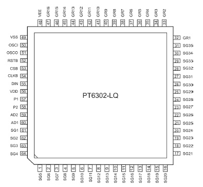
Pinout

Datasheet
http://www.ic72.com/pdf_file/p/427310.pdfNotes
Vacuum Fluorescent Displays (VFD) have been around for quite some time, but they are still popular. You will find them in audio and video equipment (eg DVD players), Point-Of-Sale stations, car displays etc. They are not cheap, unless produced in large numbers. However, they look good since they have nice bright colors and are readable in daylight. The best known types are the seven segment displays (e.g. alarmclock radios). These types can all display numbers 0-9 and some characters like A-F. The 14- or 16- segment 'starburst' displays are more suitable when you need more flexibility to display characters or symbols. The most optimal for showing characters is a dot matrix type display. This library interfaces to a Princeton PT6302 VFD controller that supports upto 16 characters in 5x7 dot matrix representation. It has internal memory for all characters and will continuously output that data to the display. The device has a built-in character ROM and supports 8 user defined characters (UDC) as well. It supports dimming (brightness control) of the display. The PT6302 has upto 2 additional segments per display position for Icons, The device also has two digital output pins. The device can be controlled by SPI bus. The Lib supports 'printf' type of output and UDCs. Note that the PT6302 and Oki ML9208 are identical.
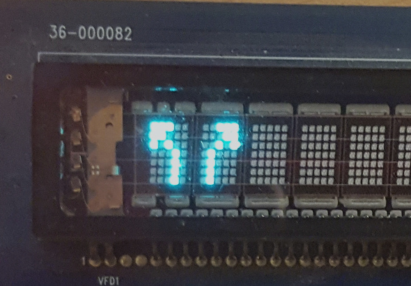
Below is an example of the PT6302 library test software for the Hannstar DVB receiver frontpanel (branded as UPC MediaBox). The frontpanel board uses a DC/DC converter to generate the VFD negative voltage and the filament voltages (upper righthand side of picture). The converter can enabled by activating one of the PT6302 digital output ports. The library provides a method to activate these portpins.

An example of two UDCs is shown below.

The general Notebook page for VFD devices is here.
You need to log in to post a discussion


