MSGEQ7 Graphic Equalizer
7-Band Graphic Equalizer chip made by Mixed Signal Integration
Hello World
Import programMSGEQ7_Hello_World
Demonstration of MSGEQ7 library interfacing with MSGEQ7 7-band Graphic Equalizer Chip made by Mixed Signal Integration.
Library
Import libraryMSGEQ7
Library used to interface to the 7-band Graphic Equalizer Chip MSGEQ7, made by company Mixed Signal Integration
Datasheet
https://www.sparkfun.com/datasheets/Components/General/MSGEQ7.pdfNotes
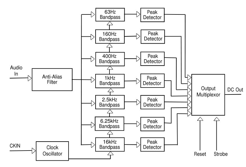
The method in which this chip operates is that inside there are 7 band-pass filters, tuned to pass 7 frequencies: 63, 160, 400, 1000, 2500, 6250, and 16000 Hz. The output of each filter is connected to a peak detector, and then a multiplexer controlled by reset and strobe lines.

At each falling edge of the strobe line, the outputs of the filter peak detectors are sequentially placed on the analog output line of the chip. At start up the chip needs to be reset, accomplished by bringing the reset line high and cycling the strobe line. After the reset line is brought low, the strobe line can then be clocked to retrieve the 7 frequencies sequentially. After all 7 frequencies have been output, the chip starts back over at the first frequency.

Note
Note that the analog output of the chip requires 36uS settling time after switching and before reading in order to get valid data.
Interfacing with the MSGEQ7
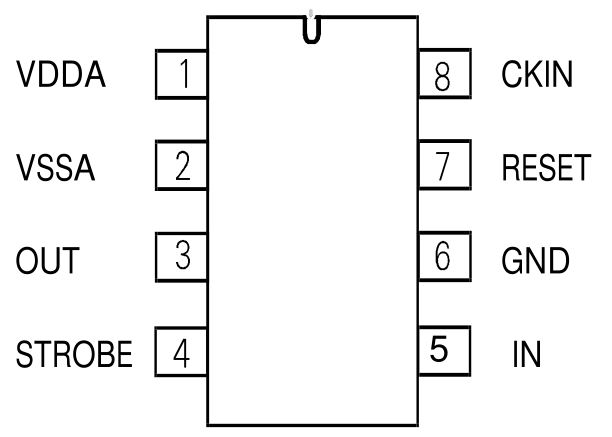
MSGEQ7 Pinout

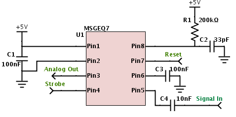
In order to use the MSGEQ7, several external components are required. The following is the minimum BOM:
- 2 - 100 nF Capacitors
- 1 - 10 nF Capacitor
- 1 - 33 pF Capacitor
- 1 - 200 kΩ Resistor
In my example circuit, I did not have a 200 kΩ resistor, so I instead used 2 100 kΩ resistors in series. The signal input in my circuit is from a 3.5mm jack, with the signal line connected to the 'ring' of the jack and the grounds connected together. Note that this is a mono design, but could be converted to a stereo design by interfacing another MSGEQ7 and connecting it to the 'tip' connection on the jack.
The following is the circuit schematic to interface the MSGEQ7 to the Mbed:

More Info
Further implementation details can be found on the initial notebook page here http://developer.mbed.org/users/chrisisthefish/notebook/mbed-audio-spectrum-analyzer/
You need to log in to post a discussion


