Adafruit MEMS Microphone Breakout - SPW2430
How to use a MEMs microphone with mbed
Hello World
Import programSPW2430_Microphone_Hello_World
Hello World for SPW2430 MEMs microphone. LEDs display audio level.
Last commit 28 Nov 2015 by  jim hamblen
Library
Import programSPW2430_Microphone_Hello_World
Hello World for SPW2430 MEMs microphone. LEDs display audio level.
Last commit 28 Nov 2015 by jim hamblen
Datasheet
http://www.knowles.com/index.php/eng/content/download/5642/89383/version/7/file/SPW2430HR5H-B.pdfNotes

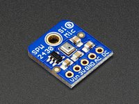
SPW2430 breakout board from Adafruit
The SPW2430 is a small, low cost MEMS mic with a range of 100 Hz - 10 kHz, good for just about all general audio recording/detection. No additional op amp is included, the output peak-to-peak voltage has a 0.67V DC bias and about 100mVpp (peak-to-peak) when talking near the microphone, which is good for attaching to something that expects 'line level' input without clipping. The peak-to-peak can be as high as 1Vpp when there is a very loud sound.
On mbed, a microphone with an amplifier with a bit higher output would provide more accuracy on the A/D and improve the signal to noise ratio, but this device is lower cost and more typical of the microphones found in new mobile devices. For the best quality audio, an external amplifier IC with a gain of around 50 is likely needed.
A Basic Microphone Hello World
The hello world demo uses the four built-in LEDs on the mbed LPC1768 to display an audio level meter. The output from the microphone is scaled up and the audio is sampled at 8kHz. An optional decoupling capacitor can be added right at the breakout board pins to reduce the analog power supply noise levels a bit.
This example will use the mbed AnalogIn and Out APIs which use floating point values with a range of 0.0 to 1.0. It would be a bit faster to scale and use the 16-bit unsigned short integer operations with AnalogIn and AnalogOut (i.e., read_u16 and write_u16) for high speed sampling, but float was used to make the demo examples a bit easier to follow.
Wiring
| mbed | microphone | (optional) 10uf decoupling capacitor |
|---|---|---|
| gnd | gnd | - |
| VU (+5VDC) | Vin | + |
| p16 (AnalogIn) | DC |
#include "mbed.h"
//Adafruit MEMs SPW2430 microphone demo
BusOut myleds(LED1,LED2,LED3,LED4);

class microphone
{
public :
    microphone(PinName pin);
    float read();
    operator float ();
private :
    AnalogIn _pin;
};
microphone::microphone (PinName pin):
    _pin(pin)
{
}
float microphone::read()
{
    return _pin.read();
}
inline microphone::operator float ()
{
    return _pin.read();
}

microphone mymicrophone(p16);

int main()
{
    while(1) {
//read in, subtract 0.67 DC bias, take absolute value, and scale up .1Vpp to 15 for builtin LED display
        myleds = int(abs((mymicrophone - (0.67/3.3)))*500.0);
//Use an 8kHz audio sample rate (phone quality audio);
        wait(1.0/8000.0);
    }
}
The response to sounds can be seen on the LED bar graph style audio level display whenever the demo is running. In this simple direct hookup mode suggested by the Adafruit documentation, it is possible to detect loud sounds.
The DC bias level might also need some minor adjustment with different devices and power supplies. The DC level does tend to drift up after loud sounds, and then slowly settle back down after a couple seconds.
Warning
When working with low level audio signals such as those found in the microphone output signal (<.1V), low noise analog design practices will be required. These include low pass filters to reduce noise on analog power supply lines, and ground planes and shields will likely be needed in a final product. As much as possible try to keep low voltage analog signals away from lines or pins with high frequency and/or high power digital signals or even AC power wires. In some cases, this may be hard to do on a breadboard and may require a custom PCB design to achieve the desired results.
Other Audio Examples
There are several other audio examples for mbed that use a microphone to record sound. For more than a couple seconds, an additional storage device is needed since RAM runs out. The built-in flash drive is just a bit too slow for recording audio. A USB flash drive or SD card can be used with a buffer and the file system drivers. There are even examples that convert the sound data to a *.wav file. For playback, there is also a *.wav file waveplayer example available. MP3 encoding/decoding uses a bit too much of the RAM on mbed. With these examples, don't forget that with the lower voltage input from this low-cost microphone, you will probably need to modify these code examples a bit to jack up the levels some before playback (or during recording).
The mPA demo
The microphone input from the A/D was sent out on the D/A to a speaker with a class D audio amp breakout board on pin 18 (drives the speaker) to build a mini mbed-based PA. The idea was to use this setup to check the quality of the audio signal obtained with digital sampling. The LEDs still indicate the microphone's audio level. At first, there were major noise problems and a constant loud hum from the speaker. But it almost works now, after adding a low pass RC filter on the microphone power input (to reduce power supply and 60Hz noise), a .1uf capacitor to ground at the analog input pin, a short or twisted pair or shielded lead (shield wire grounded) from the microphone to the A/D pin, along with a couple fixes in software to try to adjust the DC bias that drifts over time and setting unused analog input pins to digital outputs to reduce internal A/D noise. The USB cable can also add to the noise issues, so keep the leads away from it. It still has more noise than one would like to have. Keep the speaker away from the microphone or turn down the volume to avoid audio feedback problems (just like a real PA system!).
Amplifying the signal using software and the microphone's DC output
The signal from the microphone is too low to drive the speaker output. It could be amplified in software by multiplication, but the DC bias level with need to be removed first and then a DC bias of Vcc/2 can be added back in.
#include "mbed.h"
//Adafruit MEMs SPW2430 microphone demo with audio output - the "mPA"
BusOut myleds(LED1,LED2,LED3,LED4);
AnalogOut speaker(p18);
//also setting any unused analog input pins to digital outputs reduces A/D noise a bit
//see http://mbed.org/users/chris/notebook/Getting-best-ADC-performance/
DigitalOut P15(p15);
DigitalOut P16(p16);
DigitalOut P19(p19);
DigitalOut P20(p20);
class microphone
{
public :
    microphone(PinName pin);
    float read();
    operator float ();
private :
    AnalogIn _pin;
};
microphone::microphone (PinName pin):
    _pin(pin)
{
}
float microphone::read()
{
    return _pin.read();
}
inline microphone::operator float ()
{
    return _pin.read();
}

microphone mymicrophone(p17);

int main()
{
    float sample;
    float average = 0.67/3.3;//initial DC bias level
    while(1) {
//read in sample value
        sample = mymicrophone;
//subtract 0.67V DC bias - but it varies quite a bit after loud or long sounds
        average = 0.9999*average + 0.0001*sample;//try to slowly auto adjust the DC bias level
        speaker = 0.5 +((sample - average)*33.0);//scale up to 0.0 to 1.0 for speaker output
        myleds = int(abs((sample - average)*300.0)); //scale to around 15 for LEDs
//No faster than a 16kHz audio sample rate;
        wait(1.0/16000.0);
    }
}
Using the microphone's AC coupled output
Instead of attempting to adjust the DC bias in software, a minor change and a couple of resistors can do it in hardware. The AC output pin from the microphone has a series 10uf DC blocking capacitor. The microphone's AC output pin is used in this example to connect to the mbed's A/D input pin (instead of the DC pin). The AC output needs to be biased to 1.65 volts at the A/D input pin by adding both a pullup and pulldown (10K-47K? ohm) resistor (i.e., when AC=0, the input pin will be 3.3/2 or 1.65V). The inner sampling loop becomes a bit simpler now as seen in the code below.
    while(1) {
//read in sample value using AC coupled input option
        sample = mymicrophone;
        speaker = 0.5 + (sample -0.5) * 60.0;//subtract 0.5 the DC bias and amplify signal - now 1.65V external
        myleds = int(abs((sample-0.5)*300.0)); //scale to around 15 for LEDs
//No faster than a 16kHz audio sample rate;
        wait(1.0/16000.0);
    }
This is probably the best option so far. A rail-to-rail op amp could be added near the microphone to boost the voltage output level prior to the A/D conversion (gain of perhaps 50 or higher). There is still some noise present, likely from power supplies and EMI from the processor on a breadboard. Some microphones even have automatic gain control (AGC) ICs. When the mbed is in debug mode the internal analog noise is a bit higher, an interface powerdown can force it out of debug mode (but you need to hold down reset to download new code, so that can get a bit messy). The power supply noise would probably be reduced whenever batteries were used for power (less prone to 60Hz noise pickup from AC). Anti-aliasing audio low pass filters could also be added at the inputs and outputs to improve audio quality.
Given that random noise is an issue, taking a couple A/D samples and averaging the value can help just a bit. Flat out on the LPC1768 the A/D can run just under 50Khz (using AnalogIn), so there is only time to average perhaps 4 A/D input values per sample. This takes just about all of the available time, so the wait is not used. The inner loop code now becomes:
    while(1) {
//read in sample value using AC coupled input option averaging four samples
        sample = (mymicrophone + mymicrophone + mymicrophone + mymicrophone)/4.0;
        speaker = 0.5 + (sample -0.5) * 60.0;//subtract 0.5 the DC bias (now 1.65V) and add gain for speaker
        myleds = int(abs((sample-0.5)*300.0)); //scale to around 15 for LEDs
    }
It does seem to sound just a bit better, but the one disadvantage is that it now takes most of the processor time just to sample the audio signal (with the polling approach and not interrupts).
AC coupling with a microphone pre-amp
The signal levels are still a bit low for great A/D accuracy (too few bits actually change and there is a low signal to noise ratio) and a rail-to-rail op amp is probably needed for any further improvements in audio quality. The op amp circuit needed is a bit like the one on the Sparkfun MEMs microphone board (it has an obsolete microphone IC on it). Using the mic AC output, the 4.7uf DC blocking cap is already on the breakout board so that part is not needed. With the op amp circuit, the software gain from the example code would need to be reduced.
For the final improvement, a Sparkfun op amp breakout board was added to the previous circuit between the microphone AC output and the mbed A/D input to provide a gain of about 50 or so with a bandwidth of 16 Khz. The op amp breakout has a similar pullup and pulldown resistor setup to add a DC bias of Vcc/2 and the op amp should be hooked up to 3.3V power. There is a tiny gain control pot on this board (gain can be 0..100) and it was adjusted so that the output LEDs looked to be in the correct range when speaking. A very tiny 1/16 inch flat blade screwdriver is needed to adjust the pot (CCW turns gain down). Be careful when adjusting the pot it is easy to bend and make a bad connection on the pot wiper. The large software gain was removed and replaced with a gain of 2.0. Overall the audio quality improved to an acceptable level. The code change is shown below.
    while(1) {
//read in sample value using AC coupled input option averaging four samples with op amp for gain
        sample = (mymicrophone + mymicrophone + mymicrophone + mymicrophone)/4.0;
        speaker = 0.5 + (sample -0.5) * 2.0;//subtract the DC bias (1.65V) and add gain for speaker
        myleds = int(abs((sample-0.5)*30.0)); //scale to around 15 for LEDs
    }
A squelch control could also be added in software to shutdown the audio amp when no or very low audio levels are present. This would save power and also eliminate the tiny bit of noise heard on the speaker with no input on the microphone. It might also help to do something like AGC to automatically adjust the gain, but in software.
I2S
An I2S digital output microphone is another option to consider. Adafruit has one on a breakout board. Since it already has digital output, no preamp is needed. Many new MEMs microphones have I2S digital audio outputs. The I2S audio sample values are shifted out using a digital I/O pin and two clocks. LRCLK is the left/right channel select for stereo, and BCLK is the bit clock for serial data, DIN. Digital outputs provide greater noise immunity and most chips also have digital low-pass anti-aliasing filters, so higher quality audio is possible. Many processor chips such as the mbed LPC1768 have an I2S hardware controller. I2S is not one of the standard mbed APIs yet, but there are mbed I2S libraries available. An mbed demo of an I2S microphone is available at https://os.mbed.com/users/4180_1/notebook/using-an-i2s-microphone---sph0645lm4h/
PDM
There is another digital microphone standard that uses PDM (Pulse Density Modulation). It is basically a 1-bit PWM input with a clock in the Mhz range. The processor needs a PDM hardware interface. Adafruit has a PDM microphone on a breakout board.
Electret Microphone
Electret or condenser microphones are found in larger and older high quality devices. An mbed code example with a preamp IC on a breakout board is available.
You need to log in to post a discussion

Tested boards
