USB Joystick Device
The USBJoystick interface is used to emulate a joystick (gamecontroller) over the USB port. You can send throttle, rudder, and X, Y co-ordinates as well as button and hatswitch states.
Wiring
You can use an existing USB data cable and cut off one end. This typically exposes four wires, Red, Black, White and Green. On the mbed LPC1768 the USB connector should be attached as follows:
- Green USB D+ to p31
- White USB D- to p32
- Red USB 5V to Vin
- Black USB GND to GND
You can connect the USB power to VIN to power the mbed board from the Host PC when connected.
Identify the correct D+ and D- pins on other mbed boards, the ST Nucleo F411RE for example uses these pins:
- Green USB D+ to PA_12
- White USB D- to PA_11
- Red USB 5V to E5V (with jumper JP5 set to E5V)
- Black USB GND to GND
- Note that a 1k5 pullup resistor is needed between the 3v3 pin and the D+ pin or the host PC (Windows) will not recognise your board as a USB device.
- Note that on some boards the pullup is actually switched on or off by another processor pin. That allows enabling or disabling the USB communication under software control. Here is an example schematic from the mbed LPC1768 USB section.
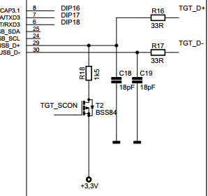
In this case the pullup is switched by T2 which is controlled by the LPC1768 chip. The Nucleo doesnt have the pullup by default. Check the hardware schematic of your (non-)mbed boards and modify accordingly.
- Note that the filtering networks 33R/18pF on D+/D- are recommended, but sometimes not present on a board.
SystemCoreClock and USB clock
- Note that the USB hardware engine needs an accurate internal clock of 48 MHz. Some (non-mbed) boards may default to a not so accurate internal oscillator that is not stable enough for reliable USB communications
- Note that the Nucleo's need a specific USB device lib to work with the Joystick lib that is presented here. The reference at the end of this page should help you get started. Some other ST F103 examples are here and here.
Hello World
USBJoystick Hello World
 #include "mbed.h"
 #include "USBJoystick.h"

 USBJoystick joystick;

 int main(void)
 {
   uint16_t i = 0;
   int16_t throttle = 0;
   int16_t rudder = 0;
   int16_t x = 0;
   int16_t y = 0;
   int32_t radius = 120;
   int32_t angle = 0;
   uint32_t buttons = 0;
   int8_t hat = 0;

   while (1) {
       // Basic Joystick
       throttle = (i >> 8) & 0xFF; // value -127 .. 128
       rudder = (i >> 8) & 0xFF;   // value -127 .. 128
       buttons = (i >> 8) & 0x0F;   // value    0 .. 15, one bit per button
       hat    = (i >> 8) & 0x07;   // value 0..7 or 8 for neutral
       i++;

       x = cos((double)angle*3.14/180.0)*radius;  // value -127 .. 128
       y = sin((double)angle*3.14/180.0)*radius;  // value -127 .. 128
       angle += 3;

       joystick.update(throttle, rudder, x, y, buttons, hat);

       wait(0.001);
   }
}
Windows Device Driver Installation
Windows will automatically install device drivers when the USB joystick device is first connected to your PC. The proper functioning of the joystick can be checked by opening the Windows Control Panel on your PC and inspecting the USB HID device list. See figure below.
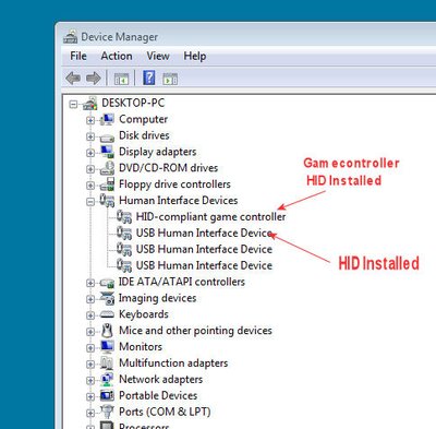
Note that you should see a new generic HID device and a specific Game controller device.
When all is well you can now find the game controller by clicking on the special gamecontroller icon in the Windows Control Panel. There should be a new Game controller. Click on its properties button and voila....
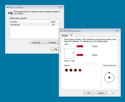
Throttle, Rudder, X,Y and the buttons/hatswitch should be constantly changing through all possible values.
Using mbed as a USB Joystick Device
You could for example use mbed analog inputs to send X, Y, throttle or rudder values to a game running on your PC. Buttons or Hat switches can reflect mbed DigitalIn pins or could be read out from I2C or SPI portexpanders. Any regular PC game that can use joysticks should be able to run with the mbed joystick emulator. You could also develop your own PC applications and access the joystick data through DirectX calls.
Developing More features
The current implementation represents a simple joystick. Additional buttons and functions can be added by modifying the USB Descriptor and adapting the 'report' structure inside the Joystick::update() method. Suppose you need 8 buttons for example. This means changing the descriptor as shown below:
... first part of descriptor goes here

// 8 Position Hat Switch
               USAGE(1), 0x39,                 // Usage (Hat switch)
               LOGICAL_MINIMUM(1), 0x00,       // 0
               LOGICAL_MAXIMUM(1), 0x07,       // 7
               PHYSICAL_MINIMUM(1), 0x00,      // Physical_Minimum (0)
               PHYSICAL_MAXIMUM(2), 0x3B, 0x01, // Physical_Maximum (315)
               UNIT(1), 0x14,                  // Unit (Eng Rot:Angular Pos)
               REPORT_SIZE(1), 0x04,
               REPORT_COUNT(1), 0x01,
               INPUT(1), 0x02,                 // Data, Variable, Absolute

#if (BUTTONS4 == 1)
// 4 Buttons
               USAGE_PAGE(1), 0x09,            // Buttons
               USAGE_MINIMUM(1), 0x01,         // 1
               USAGE_MAXIMUM(1), 0x04,         // 4
               LOGICAL_MINIMUM(1), 0x00,       // 0
               LOGICAL_MAXIMUM(1), 0x01,       // 1
               REPORT_SIZE(1), 0x01,
               REPORT_COUNT(1), 0x04,
               UNIT_EXPONENT(1), 0x00,         // Unit_Exponent (0)
               UNIT(1), 0x00,                  // Unit (None)
               INPUT(1), 0x02,                 // Data, Variable, Absolute
#endif

#if (BUTTONS8 == 1)
// 8 Buttons
               USAGE_PAGE(1), 0x09,            // Buttons
               USAGE_MINIMUM(1), 0x01,         // 1
               USAGE_MAXIMUM(1), 0x08,         // 8
               LOGICAL_MINIMUM(1), 0x00,       // 0
               LOGICAL_MAXIMUM(1), 0x01,       // 1
               REPORT_SIZE(1), 0x01,
               REPORT_COUNT(1), 0x08,
               UNIT_EXPONENT(1), 0x00,         // Unit_Exponent (0)
               UNIT(1), 0x00,                  // Unit (None)
               INPUT(1), 0x02,                 // Data, Variable, Absolute

// Padding 4 bits
               REPORT_SIZE(1), 0x01,
               REPORT_COUNT(1), 0x04,
               INPUT(1), 0x01,                 // Constant

... rest of descriptor
Note that all USB message packets from the USB device (i.e. Joystick) to the USB Host (i.e. PC) consist of a number of bytes. The bits inside the bytes are filled according to the information in the USB descriptor. There should be no 'holes' left in the descriptor. All bits must be defined. You may add padding bits if needed. The example above uses 4 bits for the hatswitch and the remaining 4 bits in the same byte for the first 4 buttons. The next byte uses 4 bits for the remaining 4 buttons and therefore also needs 4 padding bits to fill the gap. You could also modify the descriptor to instead use 4 bits for the hatswitch, then insert 4 padding bits and then use the next byte for all 8 buttons.
Windows Driver Troubleshooting!
Note that changing the descriptor also requires a new Vendor ID and/or Product ID (see Joystick constructor). That is needed because Windows links the VID/PID to a specific descriptor so that it knows which device driver should be loaded. When you change the descriptor and windows detects a mistake (eg missing or wrong bit padding) it will fail to install the USB HID driver and you probably need to use another Product ID to retry after fixing your code....
Once you have modified the descriptor, you obviously also need to modify the update method to fill the correct bits in the report message structure and set the correct report length. For example:
bool USBJoystick::update(int16_t t, int16_t r, int16_t x, int16_t y, uint32_t button, uint8_t hat) {
             HID_REPORT report;
   _t = t;
   _r = r;
   _x = x;
   _y = y;
   _button = button;
   _hat = hat;

   // Fill the report according to the Joystick Descriptor
   report.data[0] = _t & 0xff;
   report.data[1] = _r & 0xff;
   report.data[2] = _x & 0xff;
   report.data[3] = _y & 0xff;
#if (BUTTONS4  == 1)
   report.data[4] = ((_buttons & 0x0f) << 4) | (_hat & 0x0f) ;    // report byte is filled with 4 bits for buttons and 4 bits for hat
   report.length = 5;                                                               // message length is 5 bytes
#endif
#if (BUTTONS8  == 1)
   report.data[4] = ((_buttons & 0x0f) << 4) | (_hat & 0x0f) ;    // report byte is filled with 4 bits for buttons and 4 bits for hat
   report.data[5] =  (_buttons & 0xf0) >> 4;                             // report byte is filled with 4 bits for remaining buttons
   report.length = 6;                                                               // message length is now 6 bytes
#endif

   return send(&report);
}
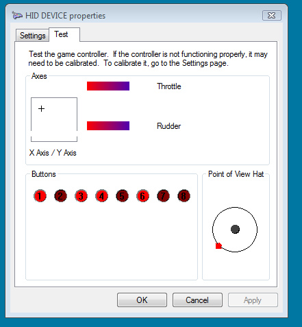
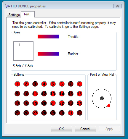
The 8 button version will look like this in the Game controller properties panel.
Wanna go over the top? Here's the 32 button version for you:
Information about the Descriptor structure can be found on http://www.usb.org/developers In particular on http://www.usb.org/developers/hidpage#HID_Usage where the HID Usage page data can be found. A usefull application note by Silicon Laboratories that explains the descriptor is here:/media/uploads/wim/hid_usb_intro_an249.pdf
The http://www.usb.org/developers page also has a USB Descriptor Tool available for download (dt2_4.zip). This tool allows you to create, edit and validate HID Report Descriptors. The tool also supports a variety of output formats (.txt, .inc, .h, etc.). (Note: I have not yet used that tool myself). When you want (ehhm.. need) to do some debugging on USB communications and device drivers the Microsoft tool USBView may be useful. It can be found for example on the FTDI site (http://www.ftdichip.com/Support/Utilities.htm). With this tool you can inspect the descriptor data that Windows received from a device.
Note that the USB HID interface can also support Mouse or Keyboard emulation (even at the same time). Obviously that requires a more compound USB Descriptor and a new update method.
Software Library and Example code
You can find the USB Joystick software here. An older (deprecated) version is here.
You can find an example of the Joystick application for an ST F411 here
Have fun!
18 comments on USB Joystick Device:
Please log in to post comments.

Hey Wim,
sorry about the post on the wiki, for some reason I seemed to have missed this page! Anyways, the 16bit joystick works just fine with some small modifications to the class and descriptor.
cheers, Ries