mbed Application Board Hands-On Demos
These examples for the application board were developed for the ARM University Program Faculty Workshop at ESWEEK 2013. They are based on selected code examples and I/O libraries posted earlier in the cookbook’s mbed application board page. Libraries used have also been updated to the most recent versions as of 9/22/13. While working through the demos, keep this web page open in one browser tab while the compiler is open in another browser tab so that it is possible to quickly switch back and forth between the two web pages. PowerPoint slides used prior to this material at the workshop to introduce mbed to faculty are also available.
Hands-On Demo 1- Blink LED
This first demo just blinks an LED on the mbed module and the application board is not required. It is the default project code for a new project in the online cloud compiler. A new user account must be setup to use the cloud compiler and the mbed module must be plugged in first to setup a new account. The mbed module appears as a USB flash drive, open the flash drive, and click on the file“mbed.htm” and follow the instructions to signup for a new account. Logon, click on the compiler link (upper right) and select new when the compiler appears. Select a name for your new program and click "OK". The project files are all stored on a cloud server. You must always logon first to use the compiler. Click “compile” and save the compiled bin file to the mbed flash drive. Hit the reset button on the mbed module, to run the most recently downloaded code. Click on “main.cpp” to view the C++ code in the compiler window. In the code, note the use of the mbed DigitalOut() and wait() APIs.
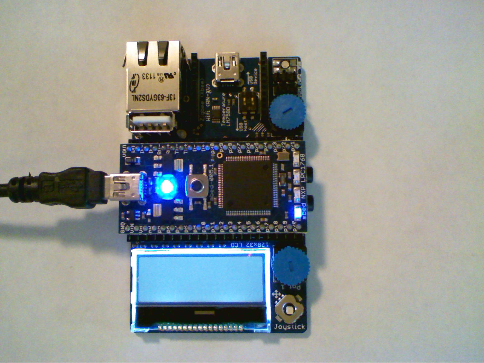
The default blink LED project
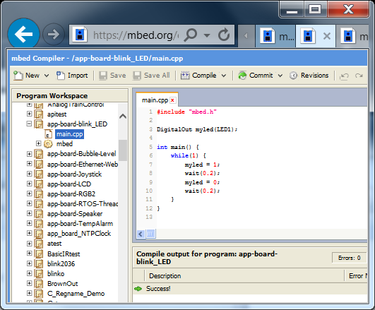
Blink LED code viewed in cloud compiler
app-board-blink_led_lpc1768.bin - has the compiled code. Save it on the mbed flash drive, hit the mbed reset button and the LED should blink.
Hands-On Demo 2 – Bubble Level
For the second demo, the mbed must first be carefully plugged into the mbed application board. Note the correct orientation in the photo below. There are also small “GND” and “VOUT” silkscreen labels on the board and mbed module that should line up (near USB cable on left in image below). There should be an extra row of black socket pins on both sides of the mbed module.
The second demo uses the board’s three axis accelerometer and the LCD display working in graphics mode to build an electronic version of a bubble level. Clicking on the “import program” link below copies all of the project files into the cloud compiler and sets up a new project. The project can then be compiled and downloaded to the mbed module. As the board is tilted, the X and Y G forces are used move the small black bubble on the display. The LCD graphics library has a handy member function to draw circles and the library code for the accelerometer returns G force readings, so the code is relatively short.
//Uses x & y acceleration to simulate a bubble level
//on the application board LCD display
#include "mbed.h"
#include "MMA7660.h"
#include "C12832_lcd.h"

C12832_LCD lcd; //On board LCD display
MMA7660 MMA(p28, p27); //I2C Accelerometer
DigitalOut connectionLed(LED1);//Accel OK LED

int main()
{
    int x=0,y=0;
    lcd.cls(); //clear LCD screen
    if (MMA.testConnection())
        connectionLed = 1; //Accelerometer init OK
    while(1) {
        //read X,Y +/-Gs and scale for #display pixels
        x = (x + MMA.x() * 32.0)/2.0;
        y = (y -(MMA.y() * 16.0))/2.0;
        lcd.fillcircle(x+63, y+15, 3, 1); //draw bubble
        lcd.circle(63, 15, 8, 1);
        wait(.1); //time delay
        lcd.fillcircle(x+63, y+15, 3, 0); //erase bubble
    }

}
Import programapp-board-Bubble-Level
This demo uses the application board’s three axis accelerometer and the LCD display working in graphics mode to build an electronic version of a bubble level.
app-board-bubble-level_lpc1768.bin - has the compiled code. Save it on the mbed flash drive and hit reset.
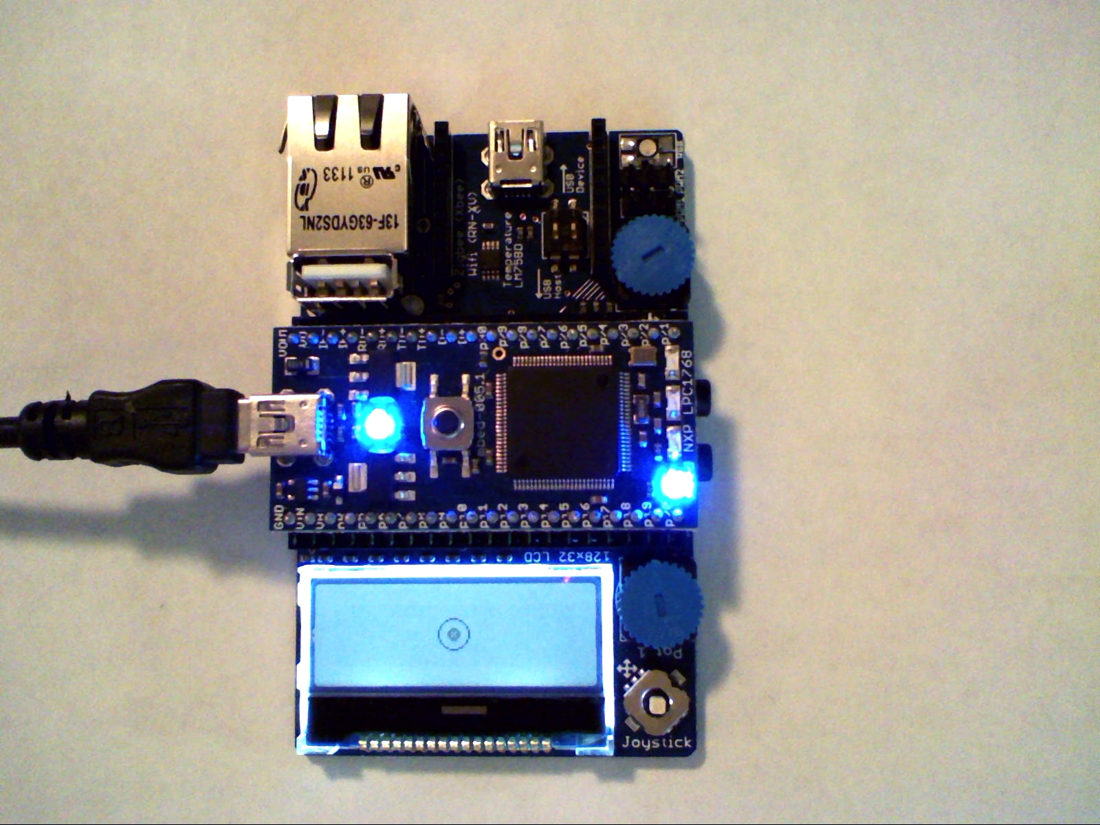
A bubble level display using accelerometer data. Tilting the board moves the solid black bubble.
Hands-On Demo 3 – Temperature Alarm
The third demo uses the board’s I2C temperature sensor to measure the board’s temperature. After a few minutes of operation, the board is typically around 5C above room temperature. The temperature is displayed on the LCD using text mode with printfs.
Pot 1 (blue dial near LCD) is used to adjust a temperature alarm setting (also shown on LCD). When the board temperature is below the alarm setting, the RGB LED is green and when it is above the RGB LED changes to RED and the speaker outputs a tone. The RGB LED and speaker are attached using hardware PWM outputs and setup using the mbed PwmOut API . The pot voltage is read in and scaled between 0.0 and 1.0 by the mbed AnalogIn API.
#include "mbed.h"
#include "LM75B.h"
#include "C12832_lcd.h"

C12832_LCD lcd; //Graphics LCD
LM75B tmp(p28,p27); //I2C Temperature Sensor
PwmOut r(p23); //RGB LED with 3 PWM outputs for dimmer control
PwmOut g(p24);
PwmOut b(p25);
PwmOut speaker(p26); //Speaker with PWM driver
AnalogIn pot1(p19); //Reads Pot 1 - near LCD
AnalogIn pot2(p20); //Reads Pot 2 - near RGB LED
Serial pc(USBTX,USBRX); //used for printf to PC over USB

int main ()
{
    float board_temp;
    float alarm_temp = 0.0;
    // generate a 800Hz tone using PWM hardware output
    speaker.period(1.0/800.0); // 800hz period
    r=1.0; //RGB LED off - PWM 100% duty cycle
    g=1.0;
    b=1.0;

    while (1) {
        lcd.cls();
        lcd.locate(0,0); //clears LCD
        board_temp = tmp; //read temperature
        lcd.printf("Board Temperature = %.2f\n\r",board_temp);
        alarm_temp = 50.0 * pot1; //read alarm temp
        lcd.printf("Temp Alarm Setting = %.2f\n\r",alarm_temp);
        if(board_temp > alarm_temp) { //check temp for alarm
            r = 1.0 - pot2; //RGB LED red
            g = 1.0;
            speaker = 0.5; //alarm tone using PWM
        } else {
            g = 1.0 - pot2; //RGB LED green
            r = 1.0;
            speaker = 0.0;
        }
        wait(1.0);
        pc.printf("%.2f\n\r",board_temp); //send temp to PC
    }
}
Import programapp-board-TempAlarm
This demo uses the application board’s I2C temperature sensor to measure the board’s temperature. Pot 1 (blue dial near LCD) is used to adjust a temperature alarm setting. Alarm uses speaker and RGB LED.
app-board-tempalarm_lpc1768.bin - has the compiled code. Save it on the mbed flash drive and hit reset.
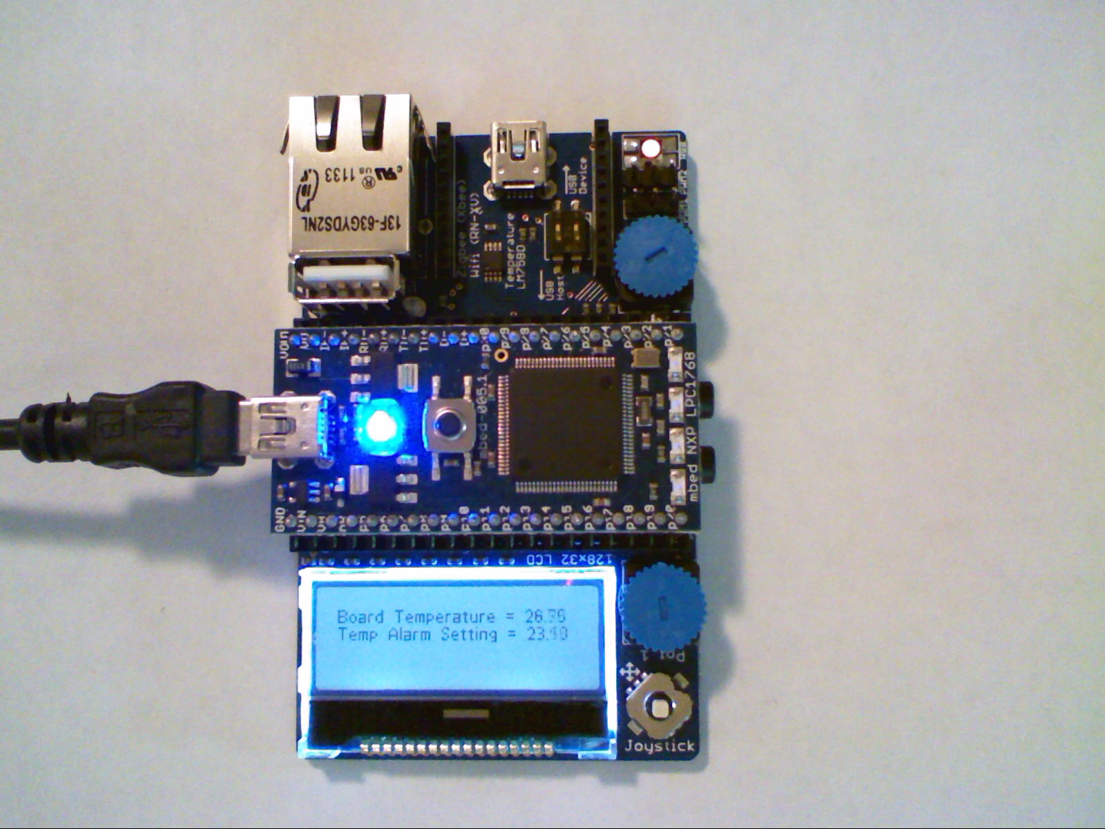
A temperature display and alarm that also sends data to the PC using printf()
Sending data to the PC in Demo 3
This demo also sends the temperature reading to the PC using a USB virtual comm port at 9600 baud. Windows users will first need to install the mbed virtual comm port driver (with the mbed module attached). A terminal application also needs to be downloaded and installed such as TeraTerm. After installing the driver and starting the mbed program, start TeraTerm, click the serial port and select the COMx port showing “mbed” in the name and click "OK"as seen below. The number of the mbed COM port will vary from PC to PC.
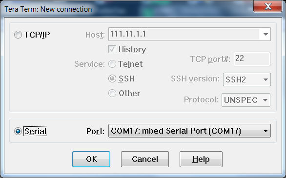
Connecting a PC terminal application to mbed's USB virtual com port
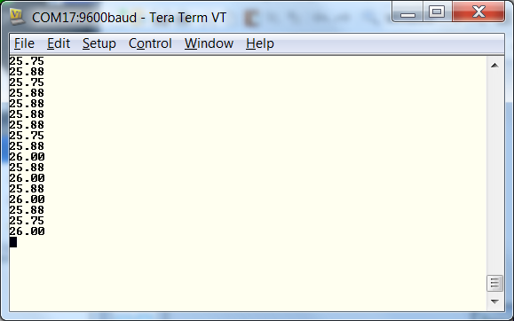
Data on a PC from mbed program's printf()s via the USB virtual com port
Macs and Linux users can use the built-in terminal and connect at 9600 baud to the mbed device. When the mbed is connected, on Macs the new mbed USB serial device name (need the number at end) can be found using the command "ls /dev/tty.usbmodem*". In Linux, use the command "ls /dev/ttyACM*". Note the mbed device name with the number included that should appear. Start a terminal application and use the command "screen yourmbeddevicename". When properly connected, you should see temperature outputs in the terminal application window from the “pc.printf()” statement in the code as shown in the image above.
In case of problems, more details can be found in the handbook's serial communication web pages. During serial data transfers, the blue power/status LED in the center of the mbed module will flicker to indicate activity.
File System Drivers
Data logging could be added to the thermostat with just a few additional lines of code. File system drivers are available for an external SD card, USB flash drives, and the mbed module’s 2M flash. More details can be found in the mbed handbook under File System. The Application Board Waveplayer Demo reads a *.wav audio file from a USB flash drive and plays it on a speaker.
Hands-On Demo 4 – RTOS and Threads
This demo uses the mbed RTOS to run eight threads (including main). The threads are using different I/O devices. Several of the threads output to the LCD and an OS mutex lock is used to control access to the LCD and make the LCD thread safe. Additional details are available in the handbook's mbed RTOS web pages.
| Thread | Function |
|---|---|
| 1 | Counts up every second and outputs count to LCD |
| 2 | Counts up every half second and outputs count to LCD |
| 3 | Displays a sine wave on LCD, speed controlled by Pot 1 |
| 4 | Reads Pot 2 and value is used to set LCD contrast |
| 5 | Displays a random color on RGB LED |
| 6 | Outputs two tone alarm sound to speaker |
| 7 | Joystick controls mbed module LEDs |
| 8 (main) | Starts other threads and outputs contrast setting to LCD |
// example to test the mbed Lab Board lcd lib with the mbed rtos
// Pot1 changes the contrast
// Pot2 changes the speed of the sin wave

#include "mbed.h"
#include "rtos.h"
#include "Small_6.h"
#include "Small_7.h"
#include "Arial_9.h"
#include "stdio.h"
#include "C12832_lcd.h"


C12832_LCD LCD;
AnalogIn Pot1(p19);
AnalogIn Pot2(p20);
PwmOut Speaker(p26);
PwmOut RGBLED_r(p23);
PwmOut RGBLED_g(p24);
PwmOut RGBLED_b(p25);
DigitalIn joyfire(p14);
BusIn joy(p15,p12,p13,p16);
BusOut leds(LED1,LED2,LED3,LED4);

// mutex to make the lcd lib thread safe
Mutex lcd_mutex;

// Thread 1
// print counter into first line and wait for 1 s
void thread1(void const *args)
{
    int i;
    while(true) {       // thread loop
        lcd_mutex.lock();
        LCD.locate(0,0);
        LCD.set_font((unsigned char*) Small_6);
        LCD.printf("Thread1 count: %d",i);
        lcd_mutex.unlock();
        i++;
        Thread::wait(1000);
    }
}

// Thread 2
// print counter into third line and wait for 0,5s
void thread2(void const *args)
{
    int k;
    while(true) {       // thread loop
        lcd_mutex.lock();
        LCD.locate(0,20);
        LCD.set_font((unsigned char*) Arial_9);
        LCD.printf("Thread 2 count : %d",k);
        lcd_mutex.unlock();
        k++;
        Thread::wait(500); // wait 0.5s
    }
}

// Thread 3
// print a sine function in a small window
// the value of pot 1 changes the speed of the sine wave
void thread3(void const *args)
{
    int i,k,v;
    double s,a;
    k = 1;
    lcd_mutex.lock();
    LCD.rect(89,0,127,17,1);
    lcd_mutex.unlock();
    while(true) {       // thread loop
        v = Pot1.read_u16();  // get value of pot 1
        lcd_mutex.lock();
        for (i=90; i<127; i++) {
            s = 8 * sin((long double)(i+k) /5);   // pixel to print
            a = 8 * sin((long double)(i+k-1) /5); // old pixel to erase
            LCD.pixel(i,9 + (int)a ,0);           // erase pixel
            LCD.pixel(i,9 + (int)s ,1);           // print pixel
        }
        LCD.copy_to_lcd();  // LCD.pixel does not update the lcd
        lcd_mutex.unlock();
        k++;
        Thread::wait(v/100);   // value of pot1 / 100
    }
}

// Thread 4
// input pot 2 and change the contrast of LCD
void thread4(void const *args)
{
    int k;
    while(true) {         // thread loop
        k = Pot2.read_u16();  // get the value of poti 2
        k = k >> 10;          // need only 6 bits for contrast
        lcd_mutex.lock();
        LCD.set_contrast(k);
        lcd_mutex.unlock();
        Thread::wait(500);    // wait 0.5s
    }
}
// Thread 5
// RGB LED
void thread5(void const *args)
{
    while(true) {         // thread loop
        RGBLED_r = 0.5 + (rand() % 11)/20.0;
        RGBLED_g = 0.5 + (rand() % 11)/20.0;
        RGBLED_b = 0.5 + (rand() % 11)/20.0;
        Thread::wait(1667);    // wait 1.5s
    }
}
// Thread 6
// Speaker
void thread6(void const *args)
{
    while(true) {         // thread loop
        Speaker.period(1.0/800.0);
        Speaker = 0.01;
        Thread::wait(1000);    // wait 1.0s
        Speaker.period(1.0/969.0);
        Speaker = 0.01;
        Thread::wait(1000);    // wait 1.0s
    }
}

// Thread 7
// Joystick controls onboard mbed LEDs
void thread7(void const *args)
{
    while(true) {         // thread loop
        if (joyfire) {
            leds = 0xf;
        } else {
            leds = joy;
        }
        Thread::wait(200);    // wait 0.25s
    }
}


int main()
{
    int j;
    LCD.cls();

    Thread t1(thread1); //start thread1
    Thread t2(thread2); //start thread2
    Thread t3(thread3); //start thread3
    Thread t4(thread4); //start thread4
    Thread t5(thread5); //start thread5
    Thread t6(thread6); //start thread6
    Thread t7(thread7); //start thread7

    while(true) {       // main is the next thread
        lcd_mutex.lock();
        LCD.locate(0,9);
        LCD.set_font((unsigned char*) Small_7);
        j = LCD.get_contrast();    // read the actual contrast
        LCD.printf("contrast : %d",j);
        lcd_mutex.unlock();
        Thread::wait(500);   // wait 0.5s
    }
}
Import programapp-board-RTOS-Threads
This demo uses the mbed RTOS to run eight threads (including main). The threads are using different I/O devices on the application board. Several of the threads output to the LCD and an OS mutex lock is used to control access to the LCD and make the LCD thread safe.
app-board-rtos-threads_lpc1768.bin - has the compiled code. Save it on the mbed flash drive and hit reset.
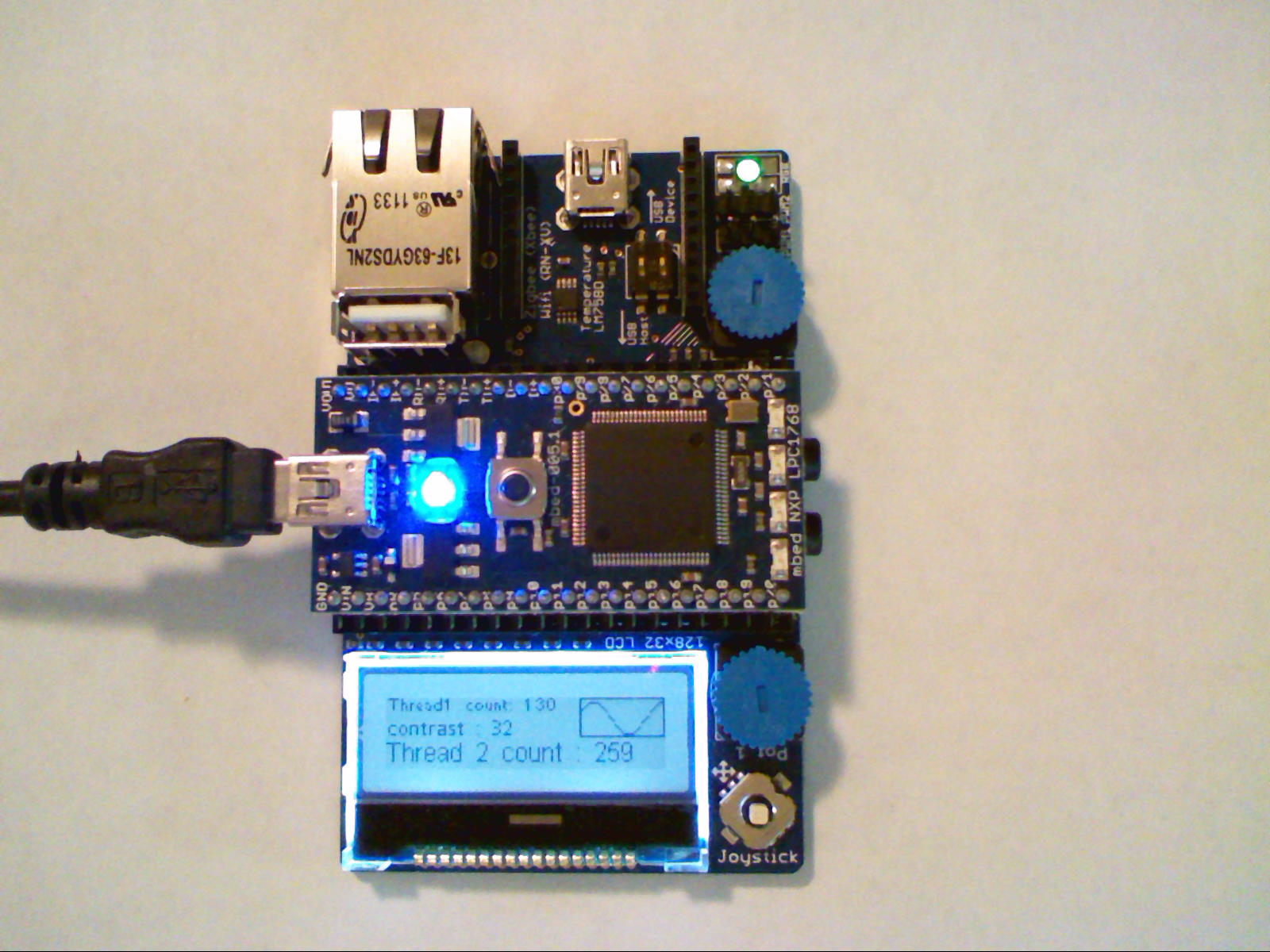
RTOS running eight threads with a mutex lock on the LCD display
Internet of Things
Instructor Demo – Internet Clock
This demo uses the TCP/IP networking stack and RTOS, to obtain the current time from an NTP server via the Internet and automatically set the mbed real-time clock. After setting the clock, the current time is displayed every second on the LCD. A network cable is required attached to a network with DHCP service enabled for the mbed module. Some networks may have security settings that require the mbed MAC address to be setup in the DHCP server. Another approach of setting up a "network bridge” can be used on any laptop that has an active Wi-Fi connection and an Ethernet jack to attach mbed to the Internet.
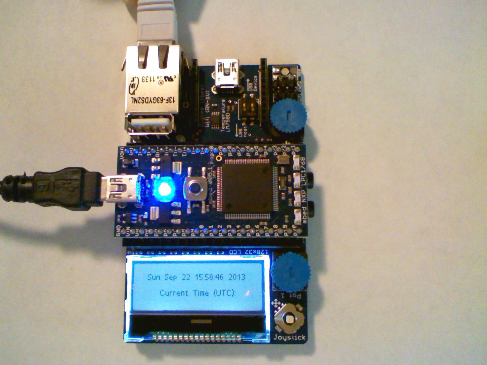
A clock automatically set to the correct time via the Internet
#include "mbed.h"
#include "EthernetInterface.h"
#include "NTPClient.h"
#include "C12832_lcd.h"

C12832_LCD lcd; //Graphics LCD
EthernetInterface eth; //Networking functions
NTPClient ntp; //NTP client

int main()
{
    eth.init(); //Init and use DHCP
    wait(2);
    lcd.cls();
    lcd.printf("Getting IP Address\r\n");
    if(eth.connect(60000)!=0) {
        lcd.printf("DHCP error - No IP");
        wait(10);
    } else {
        lcd.printf("IP is %s\n", eth.getIPAddress());
        wait(2);
    }
    lcd.cls();
    lcd.printf("Trying to update time...\r\n");
    if (ntp.setTime("0.pool.ntp.org") == 0) {
        lcd.printf("Set time successfully\r\n");
        while(1) { //update time display every second
            lcd.cls();
            lcd.locate(0,0);
            time_t ctTime;
            ctTime = time(NULL);
            lcd.printf("%s\r\n", ctime(&ctTime));
            lcd.printf("Current Time (UTC)");
            wait(1);
        }
    } else {
        lcd.printf("NTP Error\r\n");
    }
    eth.disconnect();
}
Import programapp_board-NTPclock
Clock display on app board LCD is set using an NTP network time server. DHCP service must be enabled for mbed to get an IP address. A network cable is needed.
app_board_ntpclock_lpc1768.bin - has the compiled code. Save it on the mbed flash drive and hit reset.
Instructor Demo - Websockets for Sensor Data
This example streams acceleration and temperature data from the application board to a websocket server using HTML5. Visit app-board viewer to see a real time feed when the program is running. If data does not appear, a web page reload may be needed. Various IOT cookbook pages have additional information, tutorials, and videos.
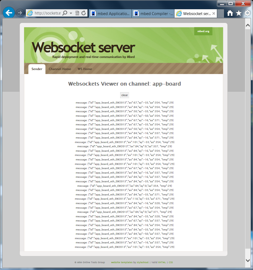
Real time sensor feed from mbed to a websocket server displayed on a web page
#include "mbed.h"
#include "EthernetInterface.h"
#include "Websocket.h"
#include "MMA7660.h"
#include "LM75B.h"

MMA7660 acc(p28, p27);// accelerometer
LM75B tmp(p28,p27);// temperature sensor
DigitalOut l1(LED1);

int main() {
    char json_str[100];
    if (acc.testConnection())
        l1 = 1;
    EthernetInterface eth;
    eth.init(); //Use DHCP
    wait(2);
    eth.connect(60000);
    printf("IP Address is %s\n\r", eth.getIPAddress());
    // See the output on http://sockets.mbed.org/app-board/viewer
    Websocket ws("ws://sockets.mbed.org:443/ws/app-board/wo");
    ws.connect();
    while (1) {
        // create json string with acc/tmp data
        sprintf(json_str, "{\"id\":\"app_board_eth_EW2013\",\"ax\":%d,\"ay\":%d,\"az\":%d, \"tmp\":%d}", (int)(acc.x()*360), (int)(acc.y()*360), (int)(acc.z()*360), (int)tmp.read());
        // send str
        ws.send(json_str);
        wait(0.1);
    }
}
Import programapp-board-Ethernet-Websocket
Websocket demo for app board by C. Styles with updated libraries. DHCP service and a network cable is required.
app-board-ethernet-websocket_lpc1768.bin - has the compiled code. Save it on the mbed flash drive and hit reset.
Websocket demo displaying live sensor data on a webpage
Instructor Demo – Offline Compiler and Breakpoints
This demo uses the ARM/Keil tools uVision (offline) compiler to show debugging with hardware breakpoints via the USB cable. It is first necessary to download and install the compiler locally on the PC. The free demo version download for Windows is limited to 32K code size, but the demo version becomes the full version with a license file or when connected to a Flex license server on the network. A firmware upgrade to the mbed module and a new USB serial driver are also required. Mixed C++ and ARM assembly language debugging is supported as well as full I/O pin level hardware emulation. An existing mbed cloud compiler project can be exported in a zip file to the offline compiler for initial setup, whenever hardware debugging using the offline compiler is required.
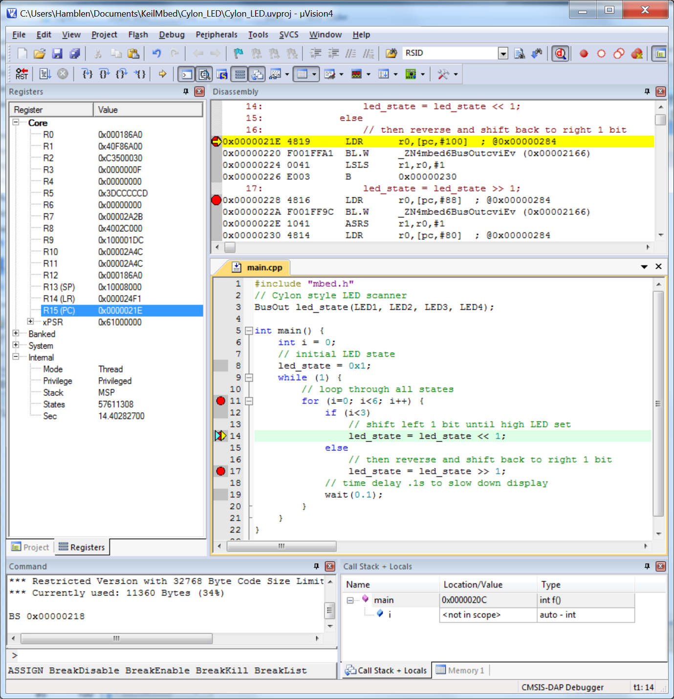
Hardware breakpoints via the mbed USB cable in the ARM/Keil tools uVision offline compiler
Video of an early test of the new breakpoint feature in the offline compiler
For more information about using mbed in a school lab see the how to set up an mbed lab checklist.
4 comments on mbed Application Board Hands-On Demos:
Please log in to post comments.

Have just tried 2 of the above demos - Internet Clock and Websockets for Sensor Data, they both worked first time and I'm very impressed!