Important changes to forums and questions
All forums and questions are now archived. To start a new conversation or read the latest updates go to forums.mbed.com.
12 years, 11 months ago.
Minimum to get LPC1768 up and running - but 12MHz Oscillator does not Oscillates?
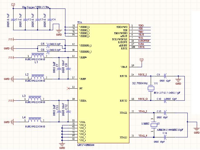 Does anybody has a very basic schematics to show me how to get the LPC1768 up and running.
I am not able to get the oscillator to oscillates. I checked the power and group pins and they are all have correct 3.3V.
Here is my the picture (Under Microscope) of my board that I populate with minimum number of component as suggested and the pin 1 is as at the lower left hand corner of the picture. Do I have the pin orientation correct? :
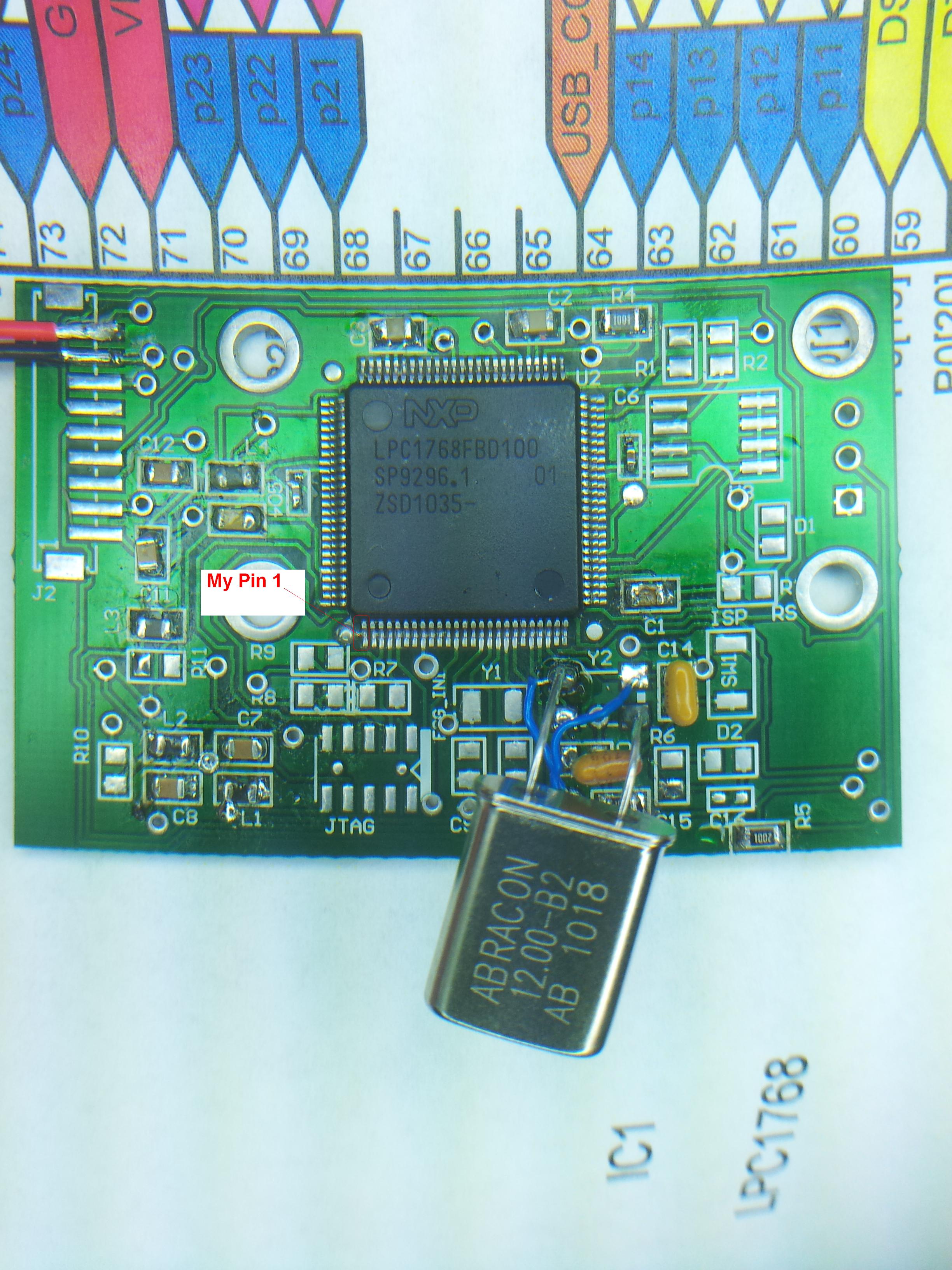
The oscillator that I cannot see any oscillation from the Oscilloscope is at Y2.
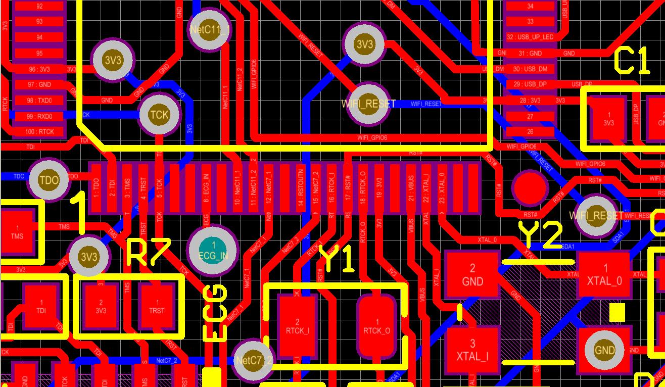
I have also spin a new board and here is my Gerber files: /media/uploads/bjsrlu/lpc1768_minimun_hardware.zip
Here is the picture of the new board:
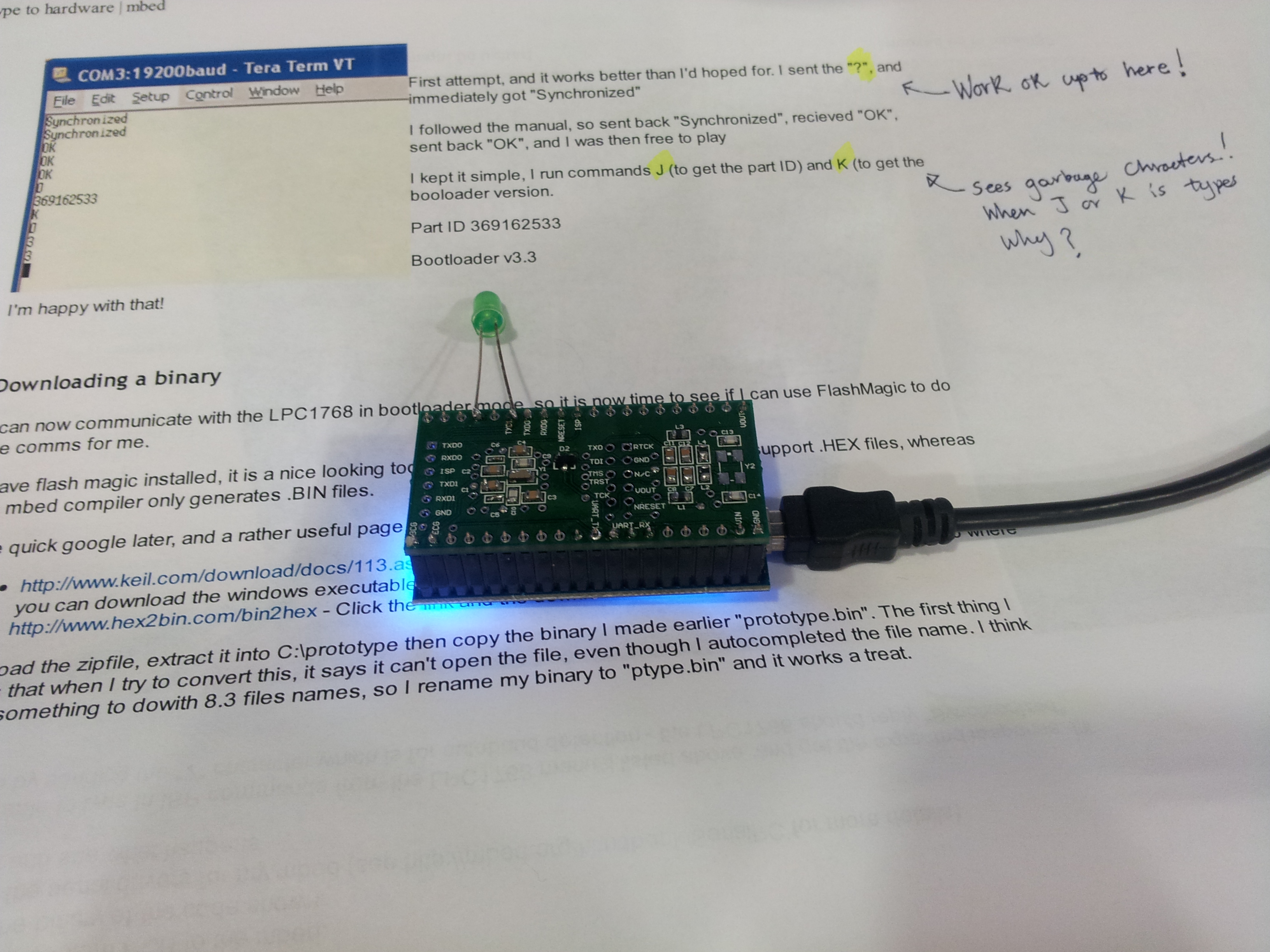
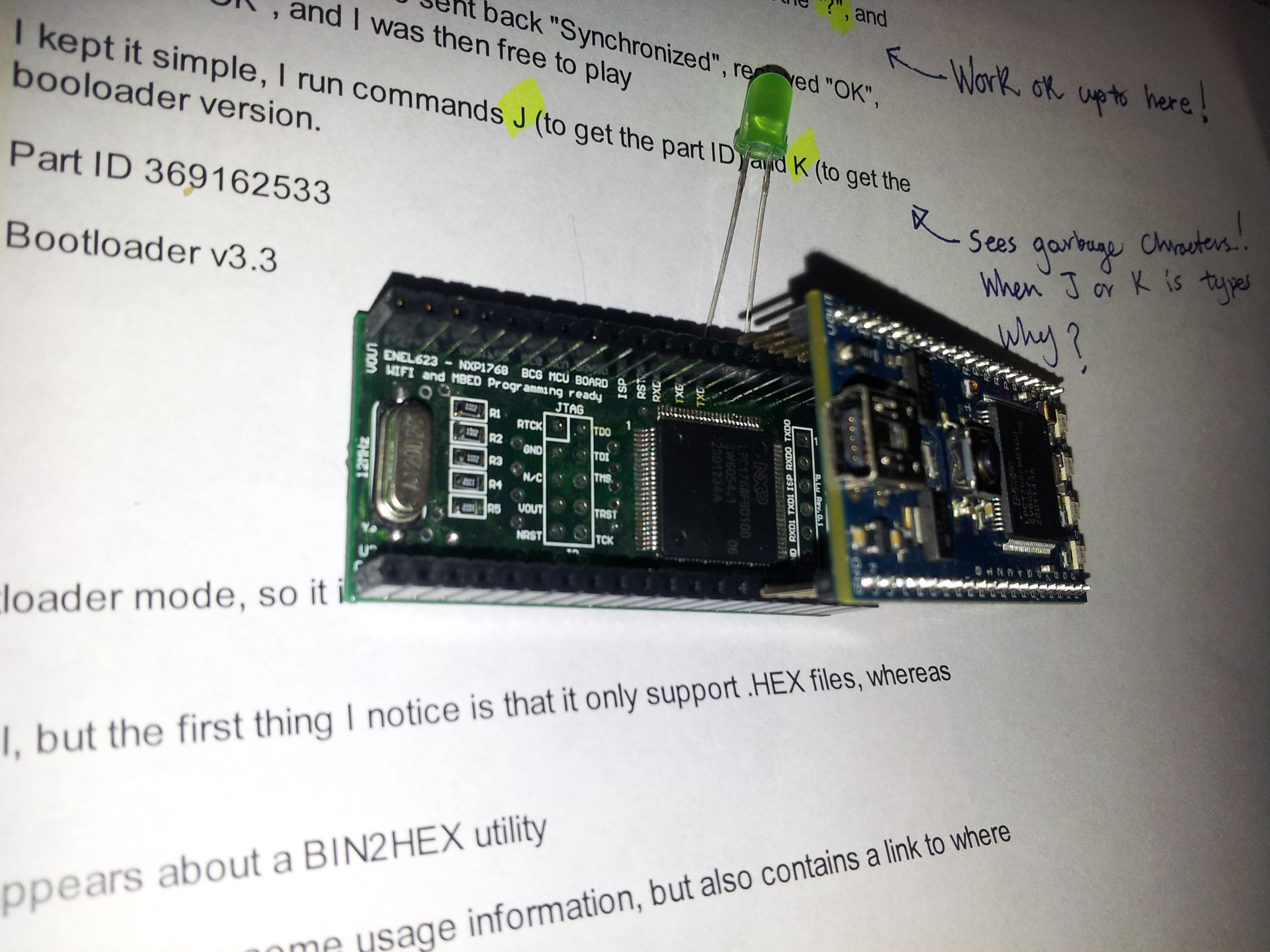
Here is the pdf file contain the schematics, layout and bill of materials: /media/uploads/bjsrlu/lpc1768_barebonerev2.1wifi.pdf
8 Answers
12 years, 11 months ago.
Looking at your photo and I see you have the Xtal soldered across the wrong set of pins?
Thanks for point that out. I originally have the surface mount ABM3B-12.000MHZ 18pF I wasn't working so I desperately trying various crystals. I tried a 7MHZ and then back to a 12.00MHZ thru hole parts. I then took a pictures while having the pin across the ground pin. I have correct that yesterday. I placed a AB-12.000MHZ-B2 across pin 1 and Pin 3 but it still doesn't oscillates.
posted by 27 Feb 20138 years, 6 months ago.
Hello there. Please can anyone suggest for me the best GSM module I can interface with LP1768.
12 years, 11 months ago.
Here's my Checklist for oscillator pathology:
1. Mounting the Crystal and its capacitors on leads can cause problems with the oscillator circuit. The leads may well present too much leakage capacitance, and series inductance. what are the blue cables for? I think those are really overdoing it. I would try to mount the correct SMD parts.
2. using a very fine probe, does the VDD supply voltage really make it to all the VDD pins? no power to the oscillator block, no osc!
3. High quality crystal is needed. check that the ESR is 40 ohm or less, and that the caps match the type of crystal.
9 years, 9 months ago.
Hello Friend,
I hope, you are informed from oscillator frequency calculate.Send a website that give information about this http://electronics.stackexchange.com/questions/121659/how-to-select-capacitor-for-a-crystal-oscillator
12 years, 11 months ago.
HI! I'am getting the same problem as you! with RC internal osc. I can get the things work! But with external xtal I can only get it work when I mod the pll0 settings to and set the frequency to 60Mhz it start to work! But with high speed it fails. I alredy tried a lot of xtal's and caps but no luck either. My setup is like Ceri one LPC mounted on a adaptor board.
12 years, 11 months ago.
Hi Robert,
Your timing is excellent.
As part of the mbed 2.0 offering, we will shortly be publishing the mbed HDK which contains the resuable design for, among others, the LPC1768 substemem implemented by mbed.
Look out for a blog post about this next week.
In the mean time, if you want a very minimal system, there are very few components you need :
- LPC1768 ;-)
- 12MHz crystal, and two 18pF capactors
- An RC reset circuit (10k/100nF)
- A pull up resistor on on the ISP pin (P0.2)
- a 100nF power supply decoupling capacitor per Vdd pin.
Until the HDK is fully available, you might want to check out this LPC1768 reference design that was published a few years ago, and represents the LPC1768 + Ethernet subsystem of mbed, i.e. no interface.
http://mbed.org/cookbook/Reference-Design
Hope this helps,
Chris
12 years, 11 months ago.
Chris, Thank you for you response. I uploaded my schematics, layout and BOM I can even upload the picture of by board if you wish. /media/uploads/bjsrlu/lpc1768.pdf
However, I am not able to get my crystal oscillate. I am not sure what's wrong. I check all power and ground pin and they have the proper supply voltages to the LPC1768 which is 3.3V. Can you tell me what I have done incorrectly?
By the way, I don't mind contributing to the HDK in some small way if possible. I have capability to create schematic, layout, and BOM and able to post my design library, schematics, and library in Altium format. I just need some help in getting my new custom hardware up and running correctly. Please advise.
Thanks, R. L.
Hi,
Had a quick look, the schematics seem fine. The things that have tripped me up in the past that might be worth checking :
- If you've soldered in SMD components, the capacitors usually don't have a value marked on them. Make very sure they really are 18pF (I tend to use 22pF). I have accidentally fitted 15pF in the past and the crystal didn't start.
- Make sure the foot print is right! The data sheet shows top view with the schematic layout, and then the bottom view with the pin identifier. A bit confusing. If you mis interpreted that, then the crystal is connected to ground, and the two ground pins would be connected to your crystal!
Are you sure the problem is the crystal (i.e. checked with the oscilloscope?). An incorrect reset circuit would also leave a system dead, as would the the ISP pin being pulled low.
Hope this helps.
Chirs
posted by 24 Feb 2013Yes, my 18pf is the ceramic 18pF 50V 5% NP0 0805 capacitor. It's part number is CC0805JRNP09BN180 (Digikey Part number 311-1102-1-ND). Just so you know I spin another board the problem is still there. I still do not see any oscillation. I did a google search and discovered that the family of LPC17xx parts all start up using the 4 MHz internal oscillator. I need to write a program that enables the oscillator, and to switch the clock source. I got this information from: https://forum.sparkfun.com/viewtopic.php?f=11&t=29481. Is that true that we need to program it to use the external clock source? Does anybody the similar experience of not able to get their 12MHz oscillator working?
posted by 27 Feb 2013In the photo (don't know if that is still relevant at this point in discussion), your capacitors are definitely NOT 0805 capacitors. Judging by their bulk, they might be a lot larger. A couple of times my students have had crystal oscillators with 18 nF capacitors.... and not surprisingly, they did not oscillate. Worth checking.
posted by 09 Oct 201312 years, 11 months ago.
have a look at some of my early posts, there are some photos of my minimal LPC1768 and
LPC11U24 as well as programming information.
also search for prototype to hardware, for an exemplary articles.
as long as you can manage to solder the package, without any shorts, or open circuits.
you should be able to get it going!
Ceri
Thank you for you input. I also have included a gerber file and schematics (see my original post). I am still unable get the oscillator oscillates. I however, able to get the "Synchronized" message by following the Prototype of Hardware by Chris Styles. However, I am unable to get the part ID and bootloader version.
posted by 27 Feb 2013