Internet LCD Clock
Setting Clocks
Manually setting clocks on all your electronic devices is such a pain. They all seem to have a different user pushbutton interface and if you don't have the manual handy, trial and error may be required. Some clocks automatically sync using a special radio time signal from an atomic clock time standard. WWV is one such example of this radio signal that is broadcast in the United States and there are even low cost ICs available to pick up this signal, but it might take several days for them to receive a strong signal indoors. If it is not located near a window, it might not ever pick up the signal. One of the more widely used WWVB receiver modules is shown below. They are found in many battery operated automatic setting wall clocks. There are several projects available on the web using the module's digital output with a microcontroller to set time. The newer triple frequency CMMR-8 module that can pick up WWVB, DCF77, JJY ,MSF, and HBG may be a bit easier to find. Despite a reputation as clockmakers, the frugal Swiss just pulled the plug on their HBG radio time transmitter to avoid costly antenna repairs and they now use the German DCF77 signal. The mbed time APIs can set and read the internal real time clock (RTC) and even convert the time to a character string for I/O.
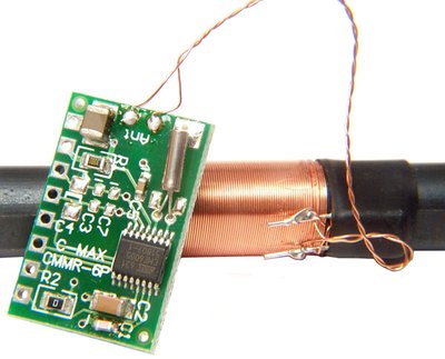
WWVB CMAX CMMR-6 receiver module with ferrite antenna
Time is also provided in GPS signals. The time can be obtained by parsing the ASCII NEMA strings output by a GPS receiver, but most devices do not have a GPS receiver and GPS will not work inside a large building. Devices such as cell phones with a GSM radio module can obtain the time from the cell service provider. TV signals contain embedded data including time. Coordinated Universal Time (UTC) is the primary time standard used to regulate clocks and time. It is one of the successors to Greenwich Mean Time (GMT). Why does Coordinated Universal Time have an acronym of UTC and not CUT? You can blame the French for saying it backwards and forcing a compromise in international standards notation.

Royal Observatory in Greenwich where time starts on the Prime Meridian.
Using NTP to set time
If an embedded device has a network connection, it can be used to set the time. This Internet of Things example features a clock that is automatically set to the correct time using a network time protocol (NTP) time server on the internet. It combines two existing cookbook code examples, NTP Client and Text LCD with a small amount of additional code. In addition to a text LCD display, a breakout board or baseboard with a ethernet jack is required. The Sparkfun Ethernet breakout board is used in the example seen below.
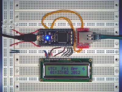
The time on the LCD is automatically set using an NTP time server on the internet. Larger Image
Wiring
Ethernet Magjack Connector
| Mbed | Sparkfun Ethernet Breakout |
|---|---|
| TD+ | P1 |
| TD- | P2 |
| RD+ | P7 |
| RD- | P8 |
Note: Different magjack connectors can use different pin outs even though they look the same. These pins are for connectors from Sparkfun in 2011. If you are having trouble with your initial network setup, try this example code first. Once it works, it will confirm correct wiring on the connector (at least on the input side). Magjack Pinouts are posted for other common connectors. More connections to the unused pins including one to 3.3V and a capacitor should be added for long cables, but this setup works well with short cables. If you still get the network error message, make sure that DHCP service is enabled for your mbed. On some networks, you need to add the module's MAC address to enable the DHCP server to give it an IP address. It times out with an error, if no IP address is returned in about fifteen seconds. If your clock sets to a strange Jul 2010 date, you may have DNS problems or a very slow network (see comments below)
Text LCD
| Mbed pins | Text LCD pins |
|---|---|
| GND | GND |
| 5V or 3.3V* | VCC |
| VO to GND via 1k resistor | |
| P15 | RS |
| GND | RW |
| P16 | E |
| N/C | D0 |
| N/C | D1 |
| N/C | D2 |
| N/C | D3 |
| P17 | D4 |
| P18 | D5 |
| P19 | D6 |
| P20 | D7 |
Where N/C is not connected and the top left pin of the TextLCD’s header is GND and the right most pin is D7 in the LCD orientation shown in the images above. The resistor sets the contrast and some LCDs may need a different value or a contrast adjust potentiometer. See Text LCD for additional help, if needed.
(*) Note: some older LCDs may use 5V, but 3.3V is more common on current LCDs. If you cannot find a data sheet to confirm this, try 3.3V first and if the display is still blank (after double checking all other connections and code) it might need 5V. To save jumper wires, this setup uses the four bit interface to transfer ASCII characters to the LCD.
Example Code
Internet_LCD_Clock
#include "mbed.h"
#include "EthernetNetIf.h"
#include "NTPClient.h"
#include "TextLCD.h"
// Internet of Things clock example: LCD time is set via internet NTP time server
TextLCD lcd(p15, p16, p17, p18, p19, p20); // rs, e, d0-d3
EthernetNetIf eth;
NTPClient ntp;

int main() {
//system time structure
    time_t ctTime;
    //clear LCD
    lcd.cls();
    // lcd.printf prints to LCD display;
    lcd.printf("Get IP addr...");
    EthernetErr ethErr = eth.setup();
    //Get an Internet IP address using DHCP
    if (ethErr) {
        //error or timeout getting an IP address
        lcd.cls();
        lcd.printf("Network Error \n\r %d",ethErr);
        return -1;
    }
    lcd.cls();
    lcd.printf("Reading Time...\n\r");
    //specify time server URL
    Host server(IpAddr(), 123, "0.uk.pool.ntp.org");
    //Read time from server
    ntp.setTime(server);
    lcd.printf("Time set");
    //Delay for human time to read LCD display
    wait(1);
    while (1) {
        // loop and periodically update the LCD's time display
        lcd.cls();
        ctTime = time(NULL);
        lcd.printf("UTC:  %s", ctime(&ctTime));
        wait(.25);
    }
}
Import programInternet_LCD_Clock
LCD clock display set using NTP server
Video Demo
Video demo of Internet LCD clock power up
In the video above, the USB cable is plugged in to power up mbed. The code connects to the DHCP server to obtain an IP address and the LCD displays "Get IP Addr...". If the cable is not connected correctly or DHCP is not enabled for the mbed device, a network error message will appear on the LCD. Everything is OK in the video, and an IP address is obtained within a few seconds. Next the code displays "Reading Time" on the LCD and contacts an NTP server to obtain the time in UTC format and it uses this data to set the real time clock. When the time is set, the LCD briefly displays "Time Set" and then enters a infinite loop where the UTC time and date is periodically updated on the LCD.
The time can also be set with the set_time API, it uses the traditional Unix seconds count since 1970. Here is handy web page that will show you the current time for use with set time, https://www.epochconverter.com/clock .
If you wire up the Internet LCD clock demo and run it, you will also want to run the weather LCD display demo, News LCD Display and Geolocation LCD Display. They use the same exact hardware setup, so you only need to download the new code.
Saving the time using battery backup
With battery backup of the real time clock (RTC) circuit, the time will not be lost and the clock will continue to run when the device is turned off or when a power outage occurs. A similar circuit is found on most PC motherboards and batteries can last a few years. Depending on the application, devices that have a reliable network connection and use NTP to set the clock might not need a battery backup on the clock. The Vb pin on the mbed module is a low current battery backup input for the real time clock (1.8-3.3V). Some early mbed modules with an extra diode draw a bit more current from the battery, but this has been fixed on newer mbeds. See http://mbed.org/users/chris/notebook/rtc-battery-backup-current/ for more information. This RTC battery calculator will predict battery life given the battery amp hour rating and RTC current load.
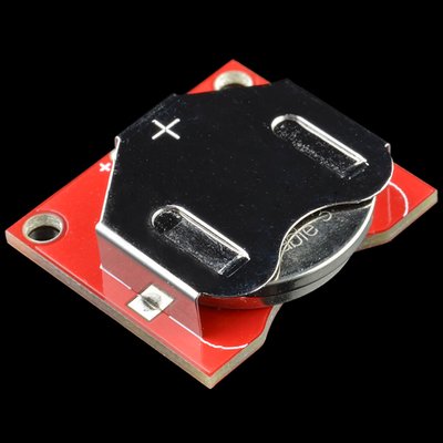
Sparkfun has a handy coin cell battery breakout board.
Rechargeable coin cell batteries are also an option. Rechargeable batteries will eventually wear out after a number of charge and discharge cycles. A typical rechargeable battery will last for only a couple hundred deep charge and discharge cycles.
In some circuits, supercapacitors can be used to replace the lithium coin cell batteries used for backup of real time clocks. Supercapacitors will work for perhaps a million charge and discharge cycles. They have a longer lifetime, but with their lower energy density will only power the circuit for several hours or perhaps days without a recharge while coin cell batteries can last weeks. Studies have shown that 99.5% of power outages are less than 4 hours. Since most power outages have a short duration, supercapacitors often have an advantage given the longer lifetime. Lithium batteries also have a limited operating temperature range and also present assembly and end of life disposal issues. There are even some hybrid circuits that try to use both supercapacitors and batteries to extract the advantages from each. In many hybrid cars, supercapacitors are used for acceleration and regenerative braking along with lithium batteries since they can store and release energy at a faster rate than batteries.
A .1f 5.5V supercapacitor such as the one seen below from VB to gnd will work for several minutes on mbed's RTC, but it also requires several minutes to fully charge. Below around 1.8V on VB with power off, the clock stops running, but the current time is saved and it will restart. When VB drops too low with power off (<.7?), the RTC locks at Jan 1 1900 until a new set_time().
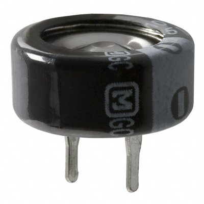
A 5.5V .1F Supercapacitor can be used for clock battery backup. Actual case diameter is 13.5mm and cost is similar to a coin cell battery.
Video Demo
Real Time clock using a supercapacitor for battery backup
In the video, the real time clock is running and note the seconds value. Near 10, the USB cable is unplugged to remove power to the mbed module and the LCD blanks out as the blue power LED goes out. After about eight seconds at 18, the USB cable is plugged back in. As the clock value reappears on the LCD note that the clock has continued to run during power off and the time and date setting was saved. The .1f supercapacitor near the upper left corner of the LCD provided backup power to the RTC circuit. The clock was first initialized using the earlier NTP demo code, and then another program was loaded for the demo once the clock was set and running. The new code for this demo does not use NTP to set the clock at power up (this code is only the while loop at end of earlier NTP demo code). If the backup battery ever runs down too low, a set_time() command will be needed to restart the clock at power on.
Using a larger supercapacitor will increase backup time, but cost and size also increases with capacitance and at some point the charge current may become too large for the power supply. Most data sheets specify the voltage rating as the maximum operating voltage and a lower voltage rating just above 3.3V (3.6 or 4V) would reduce the size and cost although a rating too low could cause problems if a voltage surge occurs. This .1f 5.5V supercapacitor is a bit easier to find off the shelf and will plug into a breadboard since the pin spacing is almost .2 inch.
Supercapcitor Charging Circuit and Backup Time
The early mbed seen in the video has a diode from Vb to 3.3V that was removed in later production mbeds. See http://mbed.org/users/chris/notebook/rtc-battery-backup-current/ for more information, photos for confirmation of missing diode, and the circuit. Later production mbeds that have the diode removed from the battery backup circuit will not charge the supercapacitor. If the supercapacitor is charged, run time increases without the diode since there is a significant reverse leakage current through the diode (it was removed for increased coin cell battery life). For a quick prototype test using a supercapacitor on the newer mbeds, add the (removed) diode from Vb to 3.3V on a breadboard or jumper it to 3.3V for a few minutes to charge it and then remove the jumper. The run time can be computed using the voltage range, capacitance, and current draw using this supercapacitor calculator. In an actual device, a more complex trickle charge circuit would likely be used to both charge the supercapacitor, and provide longer run times with lower backup current (less diode leakage). Some RTC ICs like the Maxim DS12R855 have this circuit builtin.
Chapter 27 of the LPC1768 user manual contains additional details on the RTC hardware. It is possible to calibrate the clock to improve accuracy, set an alarm using hardware, and store battery backed up data in five extra general purpose registers. These features are currently not directly available using mbed I/O APIs and it will be necessary to write directly to the registers using the register names from the mbed register definition *.h file or by directly using the register's address from the manual to use these features.
Using the RTC registers to save user data when power is off
Once the RTC runs off of battery backup, user data can be saved in the five 32-bit RTC general purpose registers (GPREG0…GPREG4) that will persist across a power cycle and will also not be cleared out by a reset. This can come in handy in some embedded device applications for a small amount of non-volatile critical data. The code seen below displays the low 4-bits of data from one of these registers in the LEDs. It then increments the register value and enters an infinite while loop. Note that the register names (i.e., "LPC_RTC->GPREG0" from LPC17xx.h) are used to directly transfer data to the hardware since this operation is not currently supported by APIs.
#include "mbed.h"
// RTC battery backed up register test
// RTC has five registers - GPREG0…GPREG4
// Should see LEDs increment on each power cycle (or reset)
DigitalOut leds[] = {(LED4), (LED3),(LED2),(LED1)};
// use leds as an array
int main() {
int i;
    // set LEDs using low 4-bits of RTC GP register 0
    for (i=0; i<4; i++) {
        leds[i] = (LPC_RTC->GPREG0>>i) &0x01;
    }
    // increment value in battery backed up RTC GP register 0
    LPC_RTC->GPREG0 = LPC_RTC->GPREG0 + 1;
    while(1) {}
}
Video Demo
Saving non-volatile data in RTC GP registers
As seen in the video above, when the RTC GP register demo code is run on an mbed with RTC battery backup power, the binary value seen in the LEDs will increment each time power is cycled on mbed. The easiest way to do this is to pull mbed’s USB cable out of your computer and plug it back in. Once power returns, the program runs again and displays the incremented value in the LEDs. A manual reset will also increment the count, since it runs the program again (but does not clear out the RTC registers). On this mbed without battery backup or the first time the program is run, all of the LEDs are on. It appears that without backup power during power off, the register values will go to all "1"s at least on this chip.
Ideas for Further Enhancements
1. Add correction for local time zone and display local time in AM/PM format. Check the handbook's mbed time APIs for help.
2. Add pushbutton(s) to set time zone.
3. Automatically resync clock late at night each day.
4. In case of a network error, delay several seconds and automatically retry.
5. Investigate using the IP address to automatically guess the local time zone.
6. Add an alarm feature with pushbuttons and a speaker. The speaker will likely need a driver circuit.
7. Use an NTP server nearer to your location.
8. Save the local time zone and alarm setting to mbed's flash file system and use it automatically at power on.
9. Use a wireless network connection with a WiFly module or other wireless device.
10. Add battery backup for the real time clock using a coin cell battery.
11. Use a supercapacitor for battery backup.
12. On power up, determine if the real time clock was still running properly off of battery backup. If it is, do not set time and use the current value.
13. Use the RTC calibration register to improve the accuracy of your clock.
14. Use one of the RTCs GPIO registers to save the time zone and alarm setting during a power loss.
15. By checking the time periodically using NTP, develop an algorithm that automatically calibrates the clock to improve accuracy.
16. Add some weather information and alerts to the clock's LCD display using a weather RSS news feed.
17. Use Power over Ethernet (PoE) to power the clock and avoid the extra wires for power. Sparkfun has one PoE option.
18. Instead of pushbuttons, use touch switch input.
19. Add a temperature sensor and add indoor temperature to the display. "lcd.locate(col,row)" will move the cursor and might come in handy.
20. Add a humidity sensor and add indoor humidity to the display.
20. Upgrade to a larger display such as a color LCD or VGA.
21. Using the speaker make a clock that chimes each hour.
22. Instead of a dull alarm, play a wave file using the speaker and perhaps an MP3 decoder.
23. Add a radio chip and make a clock radio.
12 comments on Internet LCD Clock:
Please log in to post comments.


Just flashed this code, and the date & time is wrong ..
UTC: Sat Jul 24 19:33:37 2010 UTC: Sat Jul 24 19:33:37 2010 UTC: Sat Jul 24 19:33:37 2010 UTC: Sat Jul 24 19:33:37 2010
I have tested this a few times, and always the same time !!
Is this the correct address for time ??
I do remember not being able to get this to work, as one of my first Ethernet MBED programs.
Cheers
Ceri