Vacuum Fluorescent Display (VFD) drivers
Vacuum Fluorescent Displays (VFD) have been around for quite some time, but they are still popular. You will find them in audio and video equipment (eg DVD players), Point-Of-Sale stations, car displays etc. They are not cheap, unless produced in large numbers. However, they look good since they have nice bright colors and are readable in daylight. The best known types are the seven segment displays (e.g. alarmclock radios). These types can all display numbers 0-9 and some characters like A-F. The seven segments are usually identified by the characters a-g. The same segments of all digits are usually connected together and provided as external pins and each digit is enabled or disabled by a Grid pin. In some cases the displays also feature additional segments for the decimal point (dp), colons or symbols. This multiplexed approach reduces the number of pins. VFD controllers such as the Princeton PT6312 have internal memory for all segments and will activate each digit sequentially at a high update rate (> 75 Hz) and the result is that all digits seem to be on continuously.
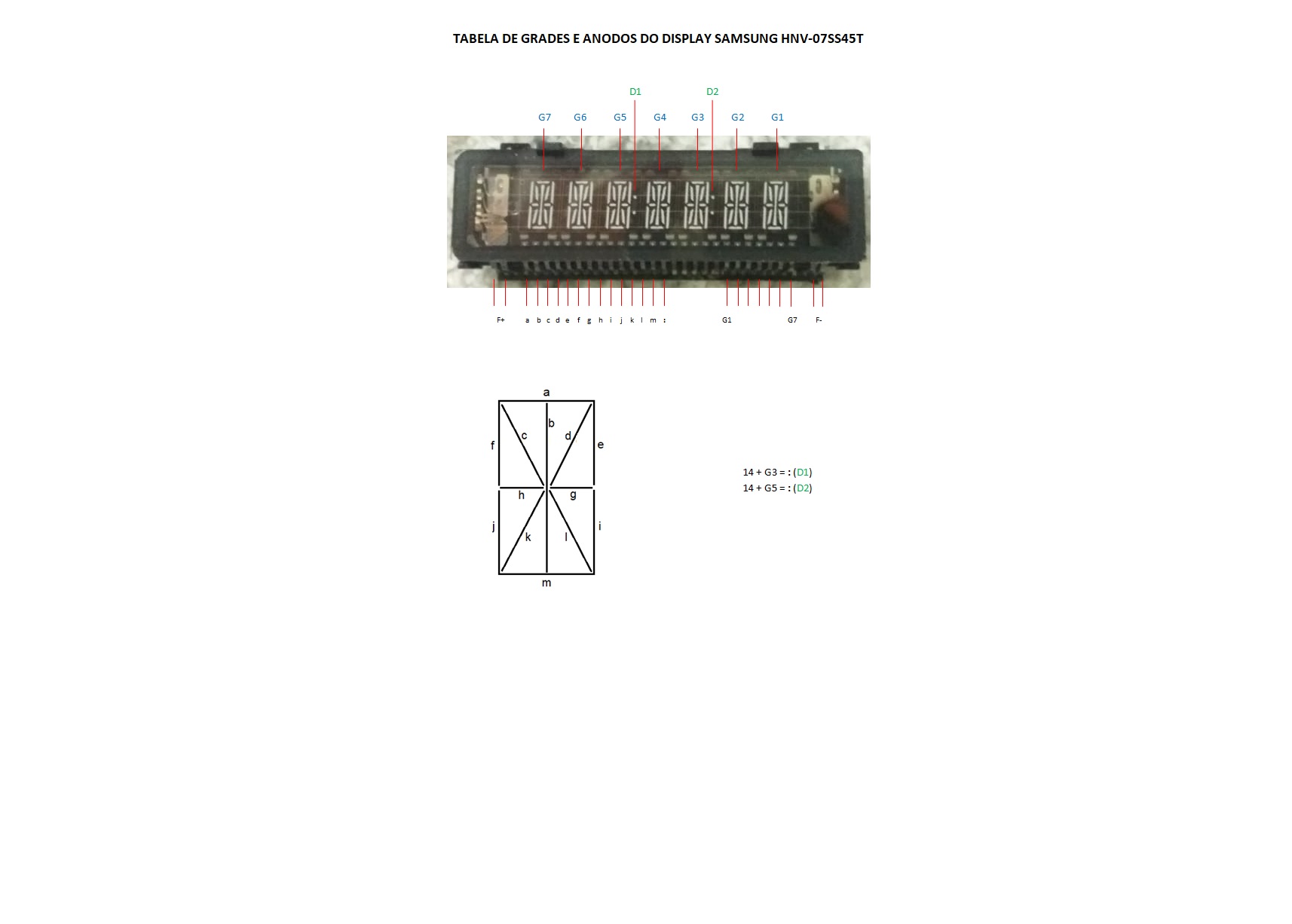
The 14- or 16- segment 'starburst' displays are more suitable than the 7 segment versions when you need more flexibility to display characters or symbols. The operating principle remains the same. Example of 14 segment character.
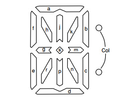
Operating principle
The VFD operation is similar to a vacuum tube or CRT. A VFD consists of a glass tube or glass box that is vacuum and airtight. The contact wires are melted into the glass body. The device has a filament of parallel wires that is heated and emits electrons. The filament also serves as cathode. The segments are formed by specific conductive shapes with a deposited layer of phosphorus material. When the segment has a positive voltage wrt to the cathode the emitted electrons will hit the phosphor and emit light. The colour depends on the type of material (typically blue/green, orange). The intensity depends on the voltage and the dutycycle.
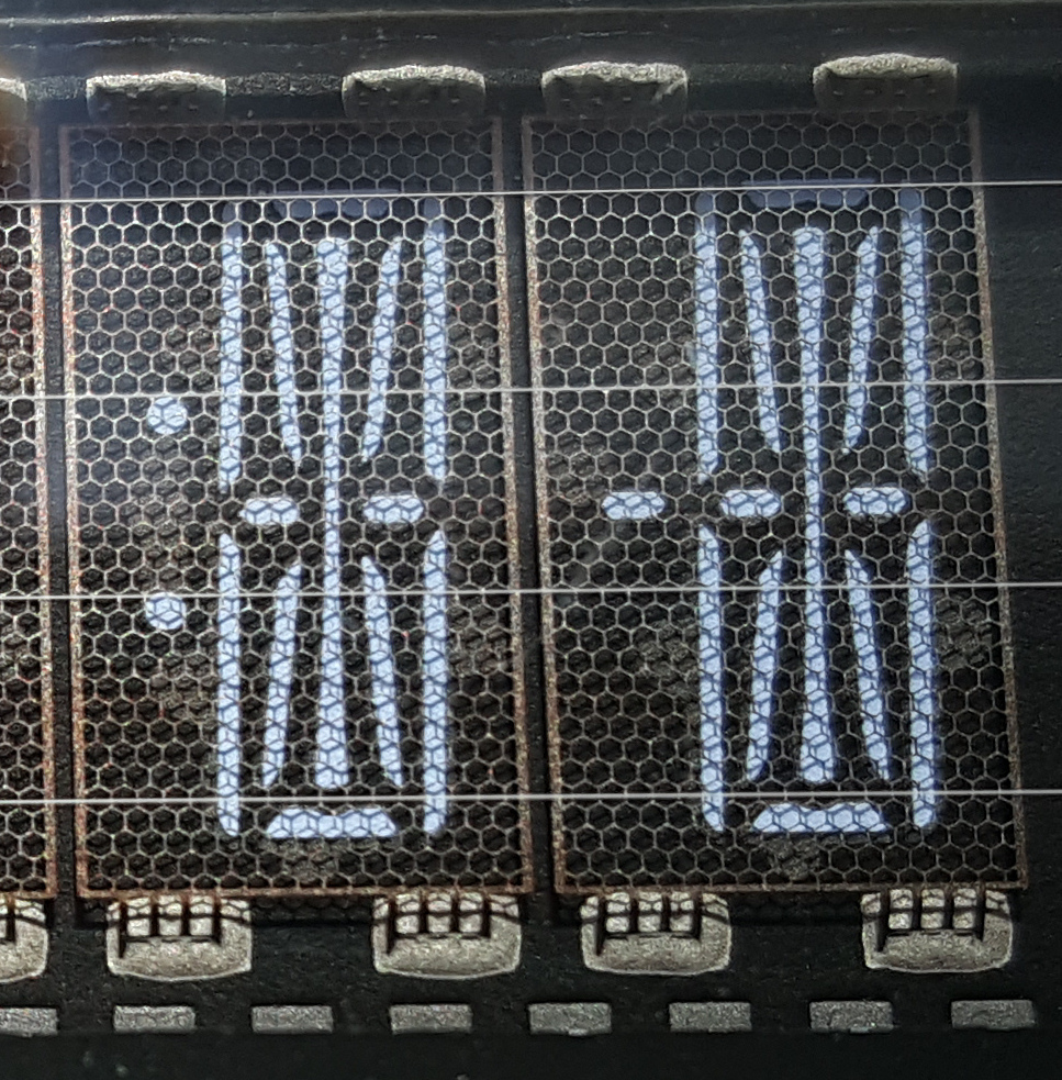
Each digit has a separate Grid in front of it. The grid looks similar to a ''chicken fence''. When the grid is positive wrt to the cathode the electrons will pass and just fly through the grid maze towards the segments. When the grid is negative wrt to the cathode the electrons are all pushed back and all segments remain dark even when they have a positive voltage. So the grids are activated one by one to multiplex all digits sequentially. The picture below shows the filament/cathode, the grids and the segments. Note that the filament is mounted on metal springs to make sure the wires remain under tension when expanding or contracting due to heating. You may be able to see a red glow when you observe the filament wires in a darkened room.
The powersupply for VFDs is a bit elaborate. Typically the most positive voltage is Vcc (5V). When the cathode reference was to be at GND this would is not be sufficient to illuminate the segments. The solution is a negative voltage of about -20V for the cathode and -25V for the de-activated Grids and segments. The cathode/filament is heated by a small AC voltage (about 3V) that is superpositioned on -20V DC.
VFD segment controller/drivers
The whole multiplex process and the high-voltage drivers are usually provided by dedicated controller/drivers such as the Princeton PT6312. This device can support multiple display modes from 4 digits of 16 segments to 11 digits of 11 segments. It has internal memory for all digits and will continuously output that data to the display. It supports dimming (brightness control) by varying the on-time of segments (duty cycle) and it has additional outputs for 4 LEDs. The device also offers 4 general purpose switch inputs and a 6x4 keyboard matrix scan. The device can be controlled by SPI bus. The diagram below shows the reference schematic for the PT6312.
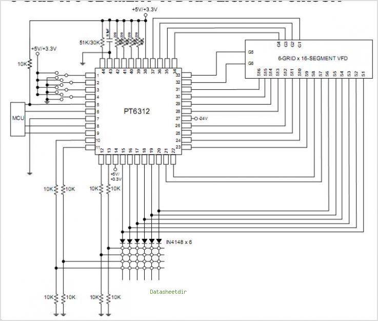
VFD segment controller/driver example
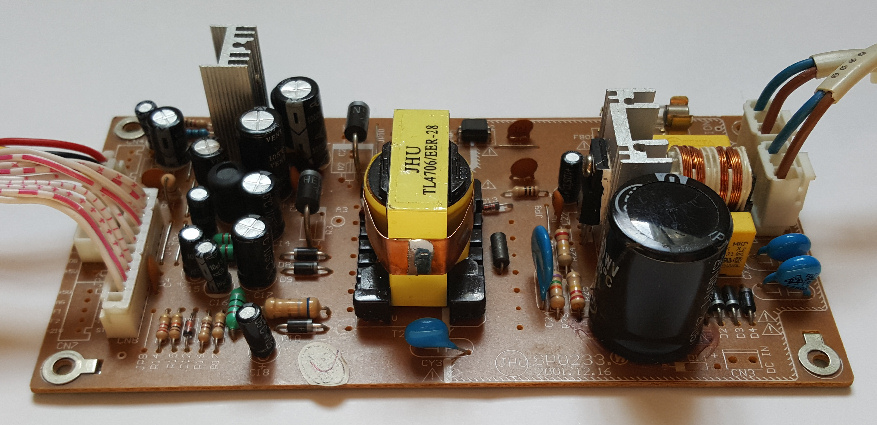
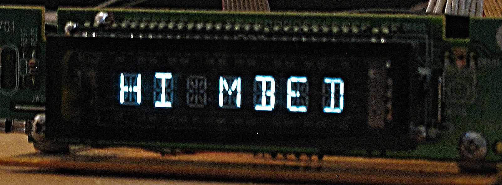
I salvaged a 7 digits 14 segment display from a Philips DVP630 DVD player and developed a software lib for mbed to drive it. The display PCB was reverse engineered and modified to simplify hooking it up to mbed. The modifications included stuff like ripping out the small cpu on the display PCB that was used to decode the IR receiver signals. The original AC switched mode powersupply was reused. I disabled the standby pin of the PSU to always switch it on.
Warning
The AC switched mode powersupply carries a dangerously high voltage. Be very careful when using it. Lethal voltages (> 250V DC) may be present for some time even after disconnecting it from AC.
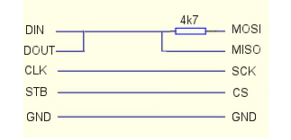
The PT6312 is controlled through an SPI port. The MOSI, MISO, SCK and CS pins of the mbed should be connected to the appropriate pins of the PT6312: DIN, DOUT, CLK and STB. Note that some PT6312 designs, like the one used in the DVP630, have DIN and DOUT shorted. This will work because the hardware never receives and transmits data at the same time and because the DOUT is actually an open collector output. The connection to mbed has to use a series resistor in the MOSI line that acts as pull-up resistor when reading back from the PT6312. See schematic:
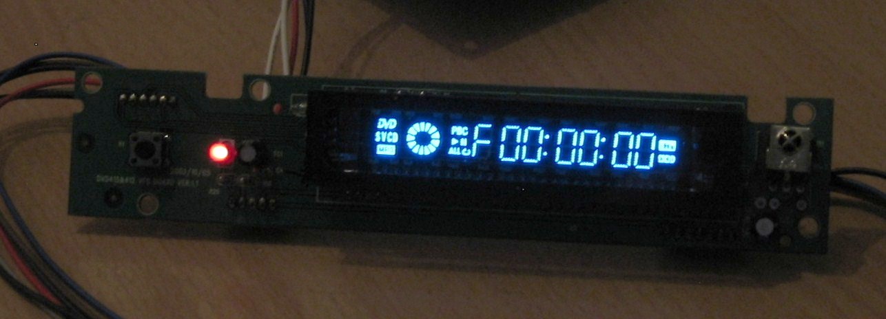
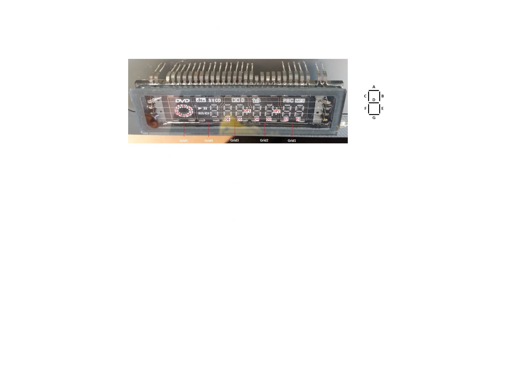
A second example is from a salvaged a 7 digits 7 segment display with several icons from a Cyberhome DVD462 DVD player. This display shows two 7 segment digits for several of its grids. Another very similar display is coded as C2233. The display PCBs were reverse engineered, but used unmodified.
Library
The lib consists of a class for a low-level PT6312 driver with basic initialisation, digit write operations, LED writes, keyscan read and inputpin reads methods. The class also supports dimming. The display configuration (number of digits/segments) is set by a parameter in the constructor.
// An interface for driving Princeton PT6312 VFD controller

// Direct driving of PT6312 Test

 #include "mbed.h"
 #include "PT6312.h"

 //DisplayData_t size is 8 bytes (4 digits @ 16 segments) ... 22 bytes (11 digits @ 11 segments)
 //DisplayData_t size default is 14 bytes (7 digits @ 15 segments)
 PT6312::DisplayData_t mbed_str = {0xDA,0x00, 0x7C,0x00, 0x3C,0x01, 0xF6,0x00, 0x00,0x00, 0x00,0x00, 0x00,0x00};
 PT6312::DisplayData_t all_str  = {0xFF,0x0F, 0xFF,0x0F, 0xFF,0x0F, 0xFF,0x0F, 0xFF,0x0F, 0xFF,0x0F, 0xFF,0x0F};

 // KeyData_t size is 3 bytes
 PT6312::KeyData_t keydata;

 // PT6312 declaration, Default setting 7 Digits @ 15 Segments
 PT6312 PT6312(p5,p6,p7, p8);

int main() {
   PT6312.cls();
   PT6312.writeData(all_str);
   wait(4);
   PT6312.writeData(mbed_str);
   wait(1);
   PT6312.setBrightness(PT6312_BRT0);
   wait(1);
   PT6312.setBrightness(PT6312_BRT3);

   while (1) {
   // Check and read keydata
     if (PT6312.getKeys(&keydata)) {
     pc.printf("Keydata 0..2 = 0x%02x 0x%02x 0x%02x\r\n", keydata[0], keydata[1], keydata[2]);

     if (keydata[0] == 0x10) { //sw2
        PT6312.cls();
        PT6312.writeData(all_str);
      }
    }
   }
}
The second part of the lib provides separate classes for the particular settings needed for three example displays: the Philips DVP630, Cyberhome DVD462 and for the display C2233. This derived classes configure the PT6312 for the correct number of segments and digits. It also supports the printf() methods since it implements Stream. In order to display ASCII characters a character fonttable is provided. The fonttable defines each character as the logical OR of all its segments. The bit that should be set for each segment is defined separately. This solution makes the fonttable flexible so you should be able to modify it for different mappings between PT6312 segment output pins and VFD glass segments.
The PT6312_DVP630 and PT6312_DVD462, PT6312_C2233 classes also supports upto 8 User Defined Characters (UDCs) that allow you to define symbols consisting of a number of selected segments. The DVP630 has only two Icons consisting of colons for digit 3 and 5. These may be set and cleared by the appropriate methods. The DVD462 and C2233 have multiple icons (eg MP3, DVD, DTS etc), including some for the pie-chart segments of a spinning DVD disc. Icons may be selected by using enumerated values as parameters for the setIcon(), clrIcon() methods. The specific derived class and its fonttable/icon definitions are selected by enabling the corresponding #define in the file "PT6312_Config.h"
//Philips DVP630 Display Test

#include "mbed.h"
#include "PT6312.h"

// KeyData_t size is 3 bytes
PT6312::KeyData_t keydata;

// PT6312_DVD declaration (7 Digits, 15 Segments)
PT6312_DVP630 DVP630(p5,p6,p7, p8);

int main() {

  DVP630.cls();
  DVP630.setBrightness(PT6312_BRT7);

 //test to show all chars

 for (int i=0x20; i<0x80; i++) {
    DVP630.cls();
    DVP630.printf("0x%2X=%c", i, (char) i);
    wait(0.2);
   //  pc.getc();
  }
}
Example of displayed string (PT6312 Philips DVP630, 7 Grids @ 15 Segments, Grids display 14 segment digits + Icon)
Example of displayed string (PT6312 Cyberhome DVD462, 6 Grids @ 16 Segments, Several Grids display two 7 segment digits + Icons)
The lib can be found on the Component page and here. The example code is here.
Similar VFD segment controllers
The PT6312 is part of a family of VFD drivers by Princeton. Similar devices exist with more/less segment and digit drivers, larger keyscan matrix etc Examples are PT6311, PT6315 and PT6320. The PT6312 device is also available from different vendors: HT16512 (Holtek), AD6312 (AnaChip), ET16312N (IRICO-AOTOM), STM68312 (ST), uPD16312 (NEC), CS16312 (Wuxi Semi), SamHop MicroElectronics (SM) or Topro (TP) are all compatible. There are libs available for several of the PT6312 family members on the Display Components page here.
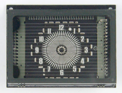
Note that VFD segments don't have to represent 7, 14 or 16 segment digits or icons, but may have almost any shape. The different segments may also have different colors.
VFD dot matrix controllers
The optimal solution for showing characters is a dot matrix type display. Examples are the Princeton PT6302 or Sanyo LC75711 controllers that support upto 16 characters in 5x7 dot matrix representation. These devices accept 8 bit ASCII codes and have a built-in character ROM to translate that code into a dot matrix pattern for the character display. They often support user defined characters (UDC) as well. The dot matrix VFD drivers typically have a serial (SPI like) interface with a proprietary command set. There are some mbed libs available for dot matrix type VFD drivers (e.g. Sanyo LC75711, see here and Princeton PT6302 see here).
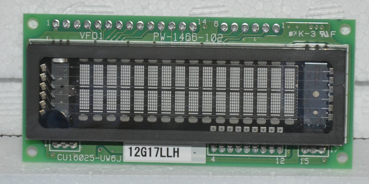
The are also VFD dot character modules with parallel or serial interfaces that behave simular to a terminal. See for example the CU209SCPB-T20A here. Note that some VFD dot matrix character controllers are also instruction compatible to the well known HD44780 LCD controller. The Enhanced TextLCD lib may be used for these displays. See here.
The next level up from dot matrix character drivers would be fully graphical VFDs, which are not further discussed here.
References
6 comments on Vacuum Fluorescent Display (VFD) drivers:
Please log in to post comments.

Whoa, you are using some pictures from my personal website ( http://magictale.com/828/a-dvd-player-hack/ ) and I don't remember you asking a permission.