An I/O controller for virtual pinball machines: accelerometer nudge sensing, analog plunger input, button input encoding, LedWiz compatible output controls, and more.

Dependencies:   mbed FastIO FastPWM USBDevice

Fork of Pinscape_Controller by Mike R

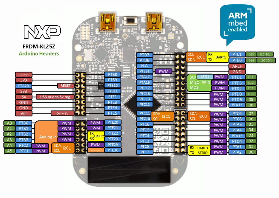
Issue: Configure a KL25Z ADC input to control the intensity of a RGB LED strip

Hello

First, thanks for the wonderful coding giving a AiO life to our virtual pinballs!

I would like to add a specific LED strip to our VP (could be called something like "audio undercab" in DOF config tool) that shows the same color as the undercab but reacts to the music volume. So I would like to wire a really simple envelope follower (with the ROM audio as the source) that would be connected to any ADC input of the KL25Z and then be used by the KL25Z to update the intensity of the"audio undercab" LED strip. The aim is to put this LED strip behind the speaker covers and have the "audio undercab" flashing according the sound.

I already did that with simple colored LEDs (you can find my tuto in French, but Google Translator does a great job and circuit diagrams are shown, here https://www.pincabpassion.net/t10010-tuto-audio-leds and a video here https://www.youtube.com/watch?v=H9Ut4l0uHUk ), but it is monochromatic and so doesn't change like "undercab".

Would it be hard to update the Pinscape_Controller source to add this function?

Thanks again David

7 comments:

23 Nov 2019

It's probably doable. I take it that what you're talking about is combining the RGB colors from the DOF undercab signal with a brightness (PWM) level taken from the ADC monitoring an audio input signal? (If you ONLY want to monitor the audio input signal, and don't care about matching the DOF colors, you really don't need to integrate with the KL25Z. I'd just use separate hardware for that as you're already doing.)

One point of conflict I see is the ADC. The KL25Z only has one ADC, and that's needed at basically 100% duty cycle for some types of plunger sensors (e.g., pot, TSL1410R). So this might be better accomplished with an external hardware add-on. I'm thinking you could use something like a Trinket or Teensy LC. Wire the RGB undercab outputs from Pinscape as three GPIO inputs to the Trinket/Teensy, and wire a separate audio input to the Trinket/Teensy ADC. Wire three Trinket/Teensy GPIO outputs to the LED strips (R,G,B).

23 Nov 2019

Thanks a lot for your answer. The KL25Z has only one ADC but 6 "Analog In" pins? https://os.mbed.com/media/uploads/GregC/frdm-kl25z_headers2.png So the KL25Z can't cope with all the A0...A5 with only 1 ADC, you mean?

So your solution is interesting, I guess I could do that with a WEMOS (I got several). How do you read the PWM signal via an input of the WEMOS? It is not a constant signal, it would mean synchronizing the WEMOS digital input with the PWM output of the KL25Z? To make things easier, wouldn't it be better to connect a KL25Z digital output to a WEMOS digital input and modify the software to send the 3 values to the WEMOS through this connection?

23 Nov 2019

The KL25Z has only one ADC but 6 "Analog In" pins?

Exactly right. It's one of those KL25Z modules (like the PWM, I2C, UART, etc) where a limited hardware resource can be multiplexed among multiple GPIO pins, but the underlying resource can only be used in one place at a time. Similar to how you can find about 25 pins marked as PWM-capable in the pin-out, but there are only 10 PWM channels (and only three distinct TPM modules underlying all of those channels). In the case of the ADC, there's only one converter, with 7 "channels", which can be multiplexed to about two GPIO pins apiece. The hardware that does the actual voltage sensing is called the "converter", and there's only one of those; you connect it to a channel through some internal ADC registers, and multiplex the channel to a GPIO pin via the multiplexer. Since there's just one converter, you can only take one sample at a time. Details about the physical hardware configuration can be found in the KL25Z Sub-Family Reference Manual:

https://www.nxp.com/docs/en/reference-manual/KL25P80M48SF0RM.pdf

When looking at the tables there, the chip that our FRDM-KL25Z dev boards use is the MKL25Z128VLK4. See in particular 3.7.1 (16-bit SAR ADC Configuration) and 28.1 et seq (Analog-to-Digital Converter [ADC]).

How do you read the PWM signal via an input of the WEMOS?

I don't what the WEMOS hardware looks like, so I couldn't tell you, but generally you'd want to using timing - measure the time of the ON period and the time of the overall cycle, and figure the proportion. One way would be to use an interrupt, which would work well if the WEMOS's interrupt latency and timer precision are a couple of orders of magnitude faster than the PWM period you're trying to time. If you're using the TLC5940 chips with the expansion board, the PWM frequency is 350kHz, so for good resolution (let's say 8 bits), you'd need to be able to measure time to about 10ns precision. That's probably a little too fast; I don't think I could get the KL25Z to do that, so assuming the WEMOS isn't a lot faster, it's probably not a reasonable thing to expect. So, indeed, this:

wouldn't it be better to connect a KL25Z digital output to a WEMOS digital input and modify the software to send the 3 values to the WEMOS through this connection?

...might be more workable. You could use a simple ad hoc two-wire (clock+data) protocol, and just add a call to the Pinscape main loop that sends out the three ports (R-G-B) of interest to your special data connection on each cycle.

I was mostly trying to suggest a way that wouldn't require modifying any of the Pinscape software, so that you wouldn't have to deal with a forked version.

24 Nov 2019

First Mike, I would like to thank you again as you are so available to help! As in France, we use the WEMOS in our virtual pinball as a Teensy to manage mainly addressable LED strips ( https://www.pincabpassion.net/t5535-tuto-pilotage-de-ledstrip-adressable-style-teensy-via-wemos-d1-pro ), I could simply just use one WEMOS directly connected to the PC. Is there a place where the communication between the DOF and the child boards is documented? I could modify the code of the WEMOS we use to manage the non-addressable LED strip but I need to know what is the serial data transfer for the 3-ports "RGB Undercab Complex" (non "MX")?

29 Nov 2019

Using a WEMOS directly with DOF is definitely a good approach - that would cut out the work of connecting the KL25Z and the WEMOS.

The challenge is going to be that there's not much documentation about DOF internals, I'm afraid. The source code is really the only "documentation". My fork of it is the most current one, since SwissLizard isn't working on it any more:

https://github.com/mjrgh/DirectOutput

However, you might not need to get too into DOF. What you could do instead is to make the WEMOS emulate one of the devices that DOF already supports. I'd probably go with the LedWiz protocol, because it's extremely simple, and it's "DOF's first language" in a way. There's some documentation available on the Web if you hunt around, although the easiest place to look might be in the Pinscape firmware source code, since I documented my extended protocol in there pretty extensively - see USBProtocol.h, and search for the part about "Real Led Wiz messages". Basically all you have to do on the WEMOS side is set up a generic USB HID device with the LedWiz VID/PID codes and 8-byte input messages. DOF will auto-discover you based on the VID/PID code and send you the 8-byte messages in the LedWiz protocol format described in USBProtocol.h. If you can find some sample code for WEMOS that sets up any sort of USB device, it should be really easy to use that as a starting point for an LedWiz emulation, since the hard part is always in setting up the USB connection in the first place.

...

I had another thought on entirely different approach that might be worth looking into. There are some external ADC chips that work well with microcontrollers, such as the Microchip MCP30xx series. Those are available in DIP packages, which makes them super easy to work with, and they don't need any external hardware. The MCP3001 only requires two pin connections to the microcontroller host (Clock In and Data Out, both digital) and has a very simple data protocol, so it would be an easy matter to read it from KL25Z code. So it would be a way to add any number of additional ADC ports to the KL25Z! It's a little extra work on the hardware side to hook up the extra chip, but given that you have to wire some circuitry to the audio channel anyway, it might be acceptable.

...

And one more alternative approach! If you're going to think in terms of adding another microcontroller to your system, you *could* always just add another KL25Z running Pinscape instead. The Pinscape firmware is happy to co-exist with multiple copies of itself in one system, so you could have Pinscape Unit #1 running your plunger, and Pinscape Unit #2 doing the audio monitoring. Unit #2 wouldn't need its analog in port for anything else, so it would be free to use for this purpose. It would be more expensive than adding the MCP3001 chip, but maybe less work.

03 Dec 2019

Thanks Mike, I've just seen your different solutions.

I did even more simple: As we have already the code for the WEMOS to be used as a TEENSY (a french tutorial is here https://www.pincabpassion.net/t5535-tuto-pilotage-de-ledstrip-adressable-style-teensy-via-wemos-d1-pro ) and so to control addressable LED strips, I just changed the code of the WEMOS to set the maximum number of LEDs in the strip as 1 (to reduce the charge and the serial transfers) and I get the color sent for "Undercab" and send it, once computed with the audio input, to the 3 channels where the R, G and B wires are connected. It was so easy, I should have thought about it before! Thanks for your time.

I am now on electronics to get a good signal at the analog input pin.

04 Dec 2019

That's a great idea - definitely a good way to adapt existing code. Good luck with it!