FIR Filtering with a Quickfilter QF1D512 Coprocessor
Introduction
Here's how to quickly (and reasonably easily) implement a fast, ultra-low power FIR filter on the mbed, using a coprocessor. You can use simple or complex high-pass, low-pass, bandpass, notch and combination filters. You don't need to be a DSP black belt, although you will probably enjoy learning more about DSP filtering by experimenting!
This post provides some mbed-specific advice, and is not intended to be a DSP tutorial, reference or FAQ, for that see dspGuru or other sources. BTW, I'm not sponsored by QuickFilter Technologies in any way; however their application engineers have been extremely helpful answering questions.
Note that FIR filters (with any hardware or software) can induce significant delay in a signal, and may not be appropriate for all applications, especially those requiring fast feedback. Factors include sample rate and and complexity of filtering required. They're great for audio processing, for example, where the data rate is high and a little latency won't crash your UAV.
The Hardware
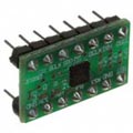
Quickfilter Technologies makes a FIR coprocessor (actually a few varieties), and it's available as a low cost ($22) DIP package that you can easily connect to mbed. You can find it on Digikey by searching for "Dipster" or "QF1D512." This post shows how to hook it up and get it running. If you're handy with soldering small surface mount packages or if your boards are built by a contract manufacturer, it's only $2.25.
There don't seem to be any other quick and inexpensive add-on filtering solutions available. Intersil has a HSP43124, but it's older, runs on 5v and is much more expensive. There are many options that are more complex, for example using DSPs, FPGAs or hybrid devices like the AD7725. Micromega sells coprocessors that handle 32-bit floating point, matrix and other operations but that is quite different, although there may be some overlap.
Compared to the CMSIS DSP Library
The CMSIS DSP library is in beta, and I haven't had time to check it out yet. The library offers many more functions than just FIR filtering, but if FIR is all you need then the QF1D512 is definitely going to have lower overhead, and you don't have to worry about managing complex data structures. However you really don't need CMSIS or a coprocessor to run a simple FIR filter in software - it's pretty easy to implement if you're not concerned about getting the best performance. And since the mbed is so fast (especially compared to 20 MHz 8-bit uCs), you can do a lot of DSP in software. The QF1D512 becomes a huge advantage over any software solution with high data rates and complex filters.
What's Good
- Simple to wire up as a single channel FIR coprocessor, or dual using two SPI ports
- Uses nearly zero processor and memory on mbed to run very complex filters (just need some minimal SPI code)
- Hides complexities of data structures, compared to doing FIR in software
- Has additional features for averaging and down-sampling
- Fast - can handle any data rate you're likely to run on an mbed (audio, definitely - but we're not talking HD video)
- Inexpensive, so you don't need to buy a more pricey dev kit, but they are available if you like
- Very low power, easily runs off the mbed 3.3v supply
- Good but basic filter design software available as free download
- I've included basic demo software listed below, for getting started
Not so Good
- Newer audio-oriented device is not available in DIP package, and you probably can't hand solder the tiny package
- Some weird design implementations for ports and memory addresses make things more complicated than necessary
- Setting up dual Dipster coprocessors to run two channels off the same SPI port is a bit tricky (QuickFilter has an example, but I haven't done it)
- Implementing a Dipster to run directly between ADC and uC is much more work than setting up for use as single coprocessor (haven't done this either)
Not Multichannel Configuration
This post describes a single channel configuration - a single QF1D512 should not be used for filtering data from multiple channels. Doing that would require flushing out all the data from one channel before feeding in the data from the next, which would take an inordinate amount of time, depending on the number of taps. I can't think of a legitimate reason for implementing something like that - you would be better off doing FIR in software or wiring up multiple QF1D512s, dedicated per channel. Or you could wire up two QF1D512 devices on two separate SPI ports.
Wiring
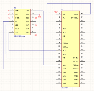
Here's how to hook it up as a single channel coprocessor (refer to the Dipster schematic) under Documentation, Product Briefs. On the mbed you will need an SPI port, plus two additional DigitalOut ports for chip select/SPI framing and QF1D512 reset. You can wire it using a breadboard, or alternately use wire wrap (my personal preference). Of course these techniques may restrict the speed you can get out of the SPI port, compared to using a printed circuit board, but it will work fine for prototyping.
- Traces: do NOT cut any traces on the Dispter
- Power: connect GND and 3.3v on the Dipster to appropriate pins on the mbed
- SPI: connect SDI-MOSI, SDO-MISO, SCK-SCK
- Control: connect separate DigitalOut pins on the mbed to CS and RST on the Dipster. You MUST use these pins! CS is not just chip select - it's used to for SPI framing, so you can't just tie it low, like on other SPI devices. Also I couldn't make the QF1D512 work unless I toggled a RST after powering everything up.
- Misc: you don't need to connect any other pins - some connections are made on the Dipster module, so this is different from using the standalone QF1D512 chip.
Design Software
QuickFilter Technologies has a decent filter design program called QuickFilter Pro that you can download; it's licensed for use with their dev kits and can be used for evaulation purposes. It's a good basic package, and will also import designs from other more fully featured programs. There are numerous ones available - this is a huge topic that I can't possibly address in a short post. MATLAB is used widely, and has the most options (including a library of custom programs written by users), but it's complicated and expensive. Free MATLAB clones are available. ScopeFIR has a UI similar to QuickFilter Pro and has many more features - you can download an eval copy and check it out. Note that different design programs may create somewhat different coefficients, given the same starting parameters. They're probably using different algorithms but the end result should be similar.
Lowpass Filter Example
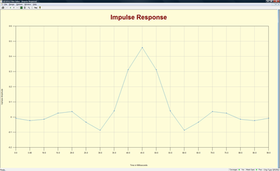
For example, you can use QuickFilter Pro to design this filter (you'll need to figure out how to use the program, it's not too difficult). Let's say you have a high resolution sensor sampling at 200 Hz and you want a cutoff frequency around 50 to 60 Hz. Realistically, you can run a 19-tap filter pretty fast on the mbed in software. The QF1D512 would be better used for something more complex.
Filter Type        : Parks-McClellan:  Lowpass
Sampling Frequency : 200.00000 Hz
Number of Taps     : 19
Coefficient Mode   : 32 bit quantized
Min Taps           : Yes
Ripple             : 1.000 dB
Attenuation        : 60.000 dB
Passband Upper     : 38.00000 Hz
Stopband Lower     : 60.00000 Hz
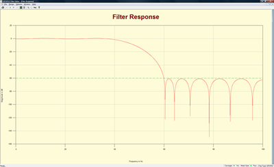
Filter Response
These charts from QuickFilter Pro show the frequency, step and impulse responses of the filter. These define exactly how the filter works (I've skipped phase response to keep this brief).
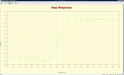
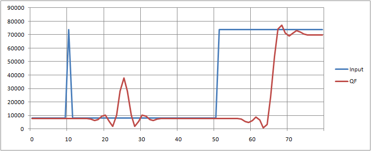
The next chart shows the output from the QF1D512 code sample below, and it matches well to the filter design. The blue line show the impulse and step of the original signal, the filter response is shown in red. Note the delay, and that the output level is not quite up to the input level. These are typical FIR issues - the gain error can easily be fixed by tweaking the filter coefficients but you need to live with the delay.
Restrictions in Example Code
There is a design issue that needs a work-around, when using the QF1D512 as a coprocessor. Because the config and data ports are connected to the same SPI bus, it's possible that a data write could change the config and coefficient registers. Clearly this would be very bad and must absolutely be prevented. The problem occurs if the first byte of data write operation corresponds to a config or coefficient register write operation (0x82 and 0x86). The easiest work around is to set the QFD512 to use 24 data bits (the max number), and then your data can be anything up to 0x820000. There are other possible solutions but this should cover the majority of cases. The downside is that excess bits are sent over SPI, but it's not a severe penalty.
This code only demonstrates basic features, and doesn't handle features such as averaging, downsampling etc.
////////////////////////////////////////////////////////////////////////////////////
// Basic demo of QF1D512 with mbed
// Use at your own risk
// This is not intended to be a full library implementation
// Tom Kreyche tkreyche@well.com
////////////////////////////////////////////////////////////////////////////////////

#include "mbed.h"

// Quickfilter functions
uint32_t QF_ReadReg( uint32_t reg );
void QF_WriteReg( uint32_t reg, uint32_t val );
uint32_t QF_ReadCReg( uint32_t reg );
void QF_WriteCReg( uint32_t reg, uint32_t val );
uint32_t QF_FilterData( uint32_t data );

//  Number of taps and coefficients in filter
#define QFTAPS 19
#define QFCOEFNUM 10

#define BASE 0x2000
#define IMPULSE 0x11FFF

// QF SPI configuration
SPI spi(p11, p12, p13); // mosi, miso, sclk

// QF chip select and reset
DigitalOut cs(p15);
DigitalOut rst(p16);

// Serial port to PC over USB
Serial pc(USBTX, USBRX); // tx, rx

////////////////////////////////////////////////////////////////////////////////////
// main
////////////////////////////////////////////////////////////////////////////////////

int main() {

    uint32_t reg = 0;
    uint32_t data = 0;

    uint32_t  QFCoef[ QFCOEFNUM ] = {
                   //   Num     Fractional
                   //   ---     ----------
    0xFEE3F1DA,    //   000   -0.008668678813
    0xFD0981E0,    //   001   -0.023147359490
    0xFE1B3CA9,    //   002   -0.014793794136
    0x03424614,    //   003    0.025460014120
    0x049E506F,    //   004    0.036081365775
    0xFBAB7589,    //   005   -0.033829982858
    0xF4D1CF82,    //   006   -0.087347089313
    0x051B9F1C,    //   007    0.039905441925
    0x27E598B1,    //   008    0.311694227625
    0x3A9C362D     //   009    0.457892200444
    };

    //short delay to let things settle
    wait_ms(100);

    // initialize SPI port, use default QF SPI config
    spi.format(8,0);
    // low SPI data rate, bump up later
    spi.frequency(500000);

    // reset the QF
    rst = 0;
    wait_ms(100);
    rst = 1;

    // config the QF
    // use 24 bit data comm to avoid problems
    // with accidental writes to config or coeff registers
    // no averaging, downsampling or header used at present

    // use symmetric filter
    QF_WriteReg(0x05, 0x02);

    // number of filter taps low bits
    QF_WriteReg(0x06, (QFTAPS - 1) & 0xFF);

    // number of filter taps high bit
    QF_WriteReg(0x07, ((QFTAPS - 1 & 0x100) >> 8));

    // only handles 24 bit data
    // to avoid problems writing over coefficient registers
    QF_WriteReg(0x0E, 0x18);

    // load coefficients
    for (int i = 0; i < QFCOEFNUM; i++) {
        QF_WriteCReg(i, QFCoef[i]);
    }

    pc.printf("\nQF Config Registers\n");
    // read QF config registers to check
    for (int i = 0; i <= 0x18; i++) {
        reg = QF_ReadReg(i);
        pc.printf("0x%02X: 0x%02X\n",i, reg);
    }

    pc.printf("\nQF Coef Registers\n");
    // read QF coef registers to check
    for (int i = 0; i < QFCOEF; i++) {
        reg = QF_ReadCReg(i);
        pc.printf("%02d: 0x%08X\n",i, reg);
    }

    // done with configuration
    // set QF to data mode
    QF_WriteReg(0x03, 0x01);

    // run impulse and step response tests
    // tests use positive offset of 0x2000

    // clean out random data in filter
    // fill with baseline
    for (int i = 0; i < 1000; i++) {
        data = QF_FilterData(BASE);
    }
    pc.printf("Impulse and step response test\n");
    // run baseline
    for (int i = 0; i < 100; i++) {
        data = QF_FilterData(BASE);
        pc.printf("%d %d\n",BASE, data);
        wait_ms(1);
    }

    // impulse response 16 bits
        data = QF_FilterData(IMPULSE);
        pc.printf("%d %d\n",IMPULSE, data);
        wait_ms(1);

    // run baseline
    for (int i = 0; i < 100; i++) {
        data = QF_FilterData(BASE);
        pc.printf("%d %d\n",BASE, data);
        wait_ms(1);
    }

    // step respsonse 16 bits
    for (int i = 0; i < 100; i++) {
        data = QF_FilterData(IMPULSE);
       pc.printf("%d %d\n",IMPULSE, data);
        wait_ms(1);
    }

}

////////////////////////////////////////////////////////////////////////////////////
// QF filter data
// only handles 24 bit SPI data transfers
////////////////////////////////////////////////////////////////////////////////////

uint32_t QF_FilterData( uint32_t data ) {

    uint32_t val[3] = {0, 0, 0};
    uint32_t fdata = 0;

    cs = 1;
    cs = 0;

    val[0] = spi.write((data & 0x00FF0000) >> 16);
    val[0] <<= 16;
    val[1] = spi.write((data & 0x0000FF00) >> 8);
    val[1] <<= 8;
    val[2] = spi.write(data & 0x000000FF);

    fdata = (val[2] | val[1] | val[0]);
    return(fdata);
}

////////////////////////////////////////////////////////////////////////////////////
// read QF config register
////////////////////////////////////////////////////////////////////////////////////

uint32_t QF_ReadReg( uint32_t reg ) {

    reg <<= 2;

    cs = 1;
    cs = 0;

    spi.write(0x83);
    spi.write(0x00);
    spi.write(reg & 0x000000FF);

    return (spi.write(0xFF));
}

////////////////////////////////////////////////////////////////////////////////////
// write QF config register
////////////////////////////////////////////////////////////////////////////////////

void QF_WriteReg( uint32_t reg, uint32_t val ) {

    reg <<= 2;

    cs = 1;
    cs = 0;

    spi.write(0x82);
    spi.write(0x00);
    spi.write(reg & 0x000000FF);
    spi.write(val);

    return;
}

////////////////////////////////////////////////////////////////////////////////////
// read QF coefficient register
////////////////////////////////////////////////////////////////////////////////////

uint32_t QF_ReadCReg( uint32_t reg ) {

    uint32_t val[4] = {0, 0, 0, 0};
    reg <<= 2;

    cs = 1;
    cs = 0;

    spi.write(0x87);
    spi.write((reg & 0x0000FF00) >> 8);
    spi.write(reg & 0x000000FF);

    val[0] = spi.write(0xFF);
    val[0] <<= 24;
    val[1] = spi.write(0xFF);
    val[1] <<= 16;
    val[2] = spi.write(0xFF);
    val[2] <<= 8;
    val[3] = spi.write(0xFF);

    return(val[3] | val[2] | val[1] | val[0]);
}

////////////////////////////////////////////////////////////////////////////////////
// write QF coefficient register
////////////////////////////////////////////////////////////////////////////////////

void QF_WriteCReg( uint32_t reg, uint32_t val ) {

    reg <<= 2;

    cs = 1;
    cs = 0;

    spi.write(0x86);
    spi.write((reg & 0x0000FF00) >> 8);
    spi.write(reg & 0x000000FF);

    spi.write((val & 0xFF000000) >> 24);
    spi.write((val & 0x00FF0000) >> 16);
    spi.write((val & 0x0000FF00) >> 8);
    spi.write(val & 0x000000FF);

    return;
}
Please log in to post comments.
