Digital Input
Example 1
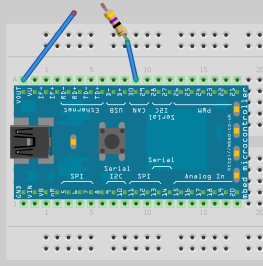
Connect as follows
| Pin in mbed | To |
|---|---|
| VOUT | Jumper Wire |
| VOUT | 47 Ω resistor |
- Observe that LED1 starts blinking when the free end of the jumper wire in contact with the free end of the resistor.
- When the connection breaks, the blinking stops.
#include "mbed.h"

DigitalIn  enable(p30);
DigitalOut myled(LED1);

int main() {
    while (1)
        if (enable) {
            myled = !myled;
            wait(0.25);
        }
}
Warning
Most of the pin in mbed board can only take up 3.3 V and 40 mA. Never connect an input with voltage larger than 3.3 V or larger than 40 mA.
Example 2
Connect as follows
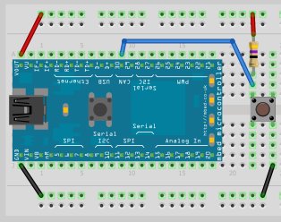
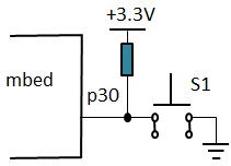
| Pin in mbed | To |
|---|---|
| VOUT | Outermost of the external track |
| GND | Innermost of the lowest track |
| Pin 30 | Side A of button -> 47 Ω resistor -> VOUT |
| Pin 30 | Side A of button -> GND |
- If the button is pressed, the digital input
enablebecomesfalse(0V). LED1 starts blinking. - When the button is released, the digital input
enablebecomestrue(+3.3V). LED1 stop blinking.
#include "mbed.h"

DigitalIn  enable(p30);
DigitalOut myled(LED1);

int main() {
    while (1)
        if (!enable) {
            myled = !myled;
            wait(0.25);
        }
}
Example 3
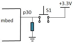
Connect as follows
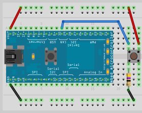
| Pin in mbed | To |
|---|---|
| VOUT | Outermost of the external track |
| GND | Innermost of the lowest track |
| Pin 30 | Side A of button -> 47 Ω resistor -> GND |
| Pin 30 | Side B of button -> VOUT |
- If the button is pressed, the digital input
enablebecomestrue(+3.3V). LED1 starts blinking. - When the button is released, the digital input
enablebecomesfalse(0V). LED1 stop blinking.
#include "mbed.h"

DigitalIn  enable(p30);
DigitalOut myled(LED1);

int main() {
    while (1)
        if (enable) {
            myled = !myled;
            wait(0.25);
        }
}
Example 4
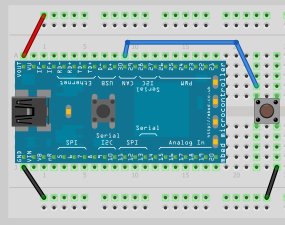
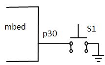
Using internal pull-up resistor, we can save external resistor and connection.
Connect as follows
| Pin in mbed | To |
|---|---|
| VOUT | Outermost of the external track |
| GND | Innermost of the lowest track |
| Pin 30 | Side A of button -> GND |
- If the button is pressed, the digital input
enablebecomesfalse(0V). LED1 starts blinking. - When the button is released, the digital input
enablebecomestrue(+3.3V). LED1 stop blinking.
#include "mbed.h"

DigitalIn  enable(p30);
DigitalOut myled(LED1);

int main() {
    while (1)
        if (!enable) {
            myled = !myled;
            wait(0.25);
        }
}
Example 5
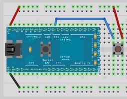
Connect as follows
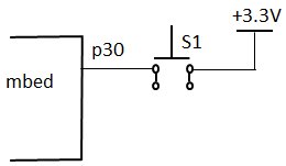
| Pin in mbed | To |
|---|---|
| VOUT | Outermost of the external track |
| GND | Innermost of the lowest track |
| Pin 30 | Side A of button -> VOUT |
- If the button is pressed, the digital input
enablebecomestrue(+3.3V). LED1 starts blinking. - When the button is released, the digital input
enablebecomesfalse(0V). LED1 stop blinking.
#include "mbed.h"

DigitalIn  enable(p30);
DigitalOut myled(LED1);

int main() {
    while (1)
        if (enable) {
            myled = !myled;
            wait(0.25);
        }
}
1 comment on Digital Input:
Please log in to post comments.

To use internal PullUp or PullDown resistors, you might use inside main function before while loop:
enable.mode(PullUp);