Xbee Remote controlled robot with telemetry
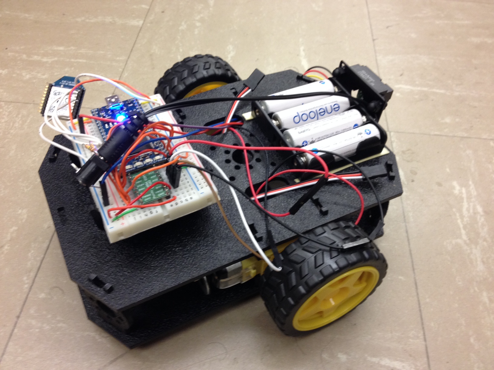
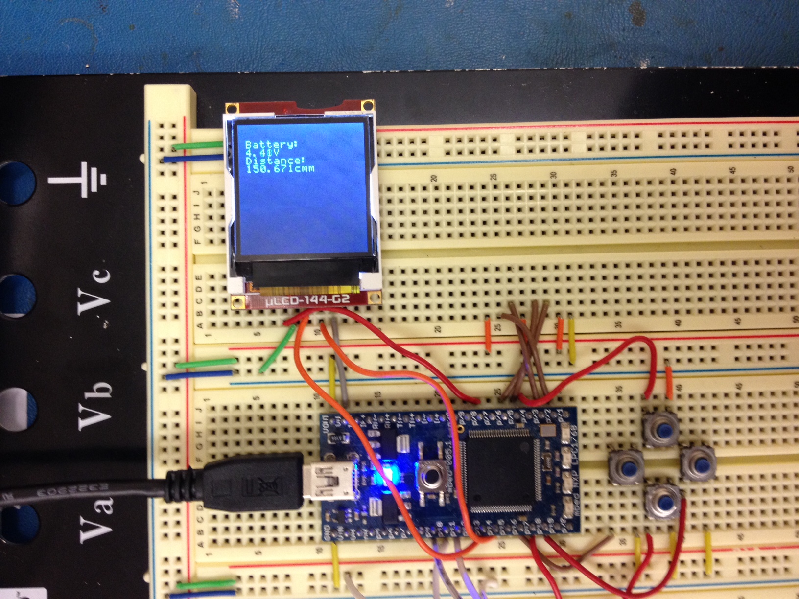
This project develops a remote controlled robot with telemetry. The robot is controlled through Xbee. It will send back the battery voltage and distance sensor information to the controller. The controller will update the information in a LCD screen in real time.
Robot:

Controller:

Team member
Hanbin Ying
Muhammad Abdullah
Alfredo Monzalvo Jr.
Description
Xbee
We use two Xbee modules (Chip number: XB24-DMWIT-250) for communication, one at the controller and one in the robot. Xbee module uses serial communication. We initialize tx/rx pins using the default Mbed serial class. All commands are a single integer.
Communication Protocol
To control the robot, we send encoded commands from the controller and the receiver decodes the command. The problem with telemetry is two-way communication. For this project, the command is so simple that it does not justify a complicated overhead for two-way communication. Therefore, we set up the communication using master/slave protocol. The master, or the controller, will always initialize the communication, either sending commands for robot movement or requesting information. The slave, or the robot, will always listen for the command. If a command is to move, it will control the motors to perform corresponding movement. If the command is to request information, it will immediately send back the requested information. Through this protocol, we greatly reduce the overhead for communication and make the communication link fast and responsive.
The ADC reading is a float between 0 and 1. Because Xbee only sends integer, we times the ADC reading by 232 and round it to an integer before sending it. The number "232" is experimentally determined to be the maximum integer that a Xbee can send reliably. We are not sure about the reason. The receiver will divide the received number by 232 to get back the original ADC reading.
Command code:
| Encoded number | =Command | Slave Action |
|---|---|---|
| 11 | forward | both motor rotates in the same forward direction |
| 12 | reverse | both motor rotates in the same forward direction |
| 13 | left | right motor rotates faster and left motor rotates slower |
| 14 | right | left motor rotates faster and right motor rotates slower |
| 15 | battery | send back the battery voltage read from ADC |
| 16 | distance sensor | send back the distance sensor reading from ADC |
Distance sensor
We use a Sharp IR distance sensor placed in the front of the robot. It is a pretty nice and responsive sensor that converts the distance to a 0-3.3V analog voltage. The inverse distance is linearly related to the analog voltage, as shown in the graph. We use a linear approximation to scale the inverse voltage to a centimeter reading.
Datasheet: (http://sharp-world.com/products/device/lineup/data/pdf/datasheet/gp2y0a21yk_e.pdf)

Battery Reader
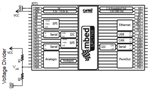
A resistive divider (150k, 150k) is used to scale battery voltage down and read into ADC. The voltage is read by Analogin at pin 20 of the mbed. The circuitry is shown below. The voltage divider is used to drop the battery voltage (Vcc) to a safe, readable level. The battery information is then transmitted via Xbee and displayed on LCD. We use 4 rechargeable Eneloop NiMH AA batteries for a total of 5.2V. They power two motors, the Mbed, and the distance sensor. The battery is very strong. We did all testing on the robot for a month, and the battery only drops to around 5V, still enough to power everything fine.

LCD
The LCD display is the 128*128 uLCD from L3. We use RTOS to update the information once every 0.3s. There is a mutex lock on the distance or voltage variable. The reason is that, when the LCD is trying to accessing the global variable, the variable should not be updated by other routines in the meantime. Without the mutex lock, the thread will crash. This mutex lock also makes sure only one process is accessing the LCD at the same time.
Wiring Diagram
The wiring of the Xbee is shown below. The Mbed pin number can be changed as long as they satisfy the requirement. One important thing to note is that Xbee module has a smaller pitch than 0.1'. It needs an adapter https://www.sparkfun.com/products/11812) if users want to install it on a breadboard.
Controller pinout:
| Xbee # | Xbee pin name | Mbed | LCD |
|---|---|---|---|
| 1 | VCC | 3.3V | |
| 2 | Dout | rx (p10) | |
| 3 | Din | tx (p9) | |
| 5 | Reset | DigitalOut (p11) | |
| 10 | GND | GND | |
| others | not connected | ||
| tx (p13) | tx | ||
| rx (p14) | rx | ||
| p28 | reset | ||
| GND | GND | ||
| VU (5V) | 5V |
Slave pinout:
| mbed | H-bridge | Motor |
|---|---|---|
| gnd | gnd | |
| Vout | Vcc | |
| Vout | /STBY | |
| VU(5V)* | Vmot | |
| p26 | PWMA | |
| p25 | AIN2 | |
| p23 | BIN1 | |
| p22 | BIN2 | |
| BO1 | RIGHT-BLK | |
| BO2 | RIGHT-BLK | |
| AO2 | LEFT-BLK | |
| AO1 | LEFT-RED |
Video Demo
Controller Demo
The video demo the communication between master and slave Xbees which are present at controller and robot respectively. Control inputs for various manuevers of the car are requested at the controller and the the desired actions are executed by the robot.
Telemetry
This video specifically shows how the required information is sent back to the master and gets displayed in the uLCD. When the master sends the encoded signal to request battery voltage and sensor information, the values are sent by the slave and are stored in the variables. A separate routine periodically updated the value on the LCD.
Demo Code for Controller
This is the demo code for controller.
Import program2Xbee_Controller1
Xbee robot with telemetry, controller code
Demo Code for Robot
This is the demo code for the robot.
Import program2Xbee_Robot
Xbee robot with telemetry, robot code
Please log in to post comments.
