4180 Design Project: M3pi Robot with Bluetooth, LIDAR and Solenoid Ping Pong Launcher
Alexander Saad-Falcon, Xavier Williams, Richard Huckaby, Emily Backer
M3pi Robot
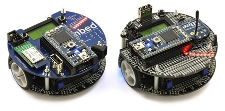
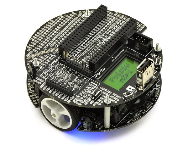
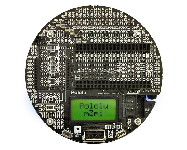
The Pololu m3pi robot consists of a 3pi robot base with a fully assembled m3pi expansion board as it second level. The expansion board enables the use of a powerful 32-bit mbed development board as the robot's high-level controller. The mbed offers more processing and free I/O pins lines than the 3pi's built in 8-bit AVR microcontroller. The mbed communicates with the m3pi robot via I2C. Pin 9 and Pin 10 are the pins the mbed uses to talk to the robot.
LIDAR Sensor
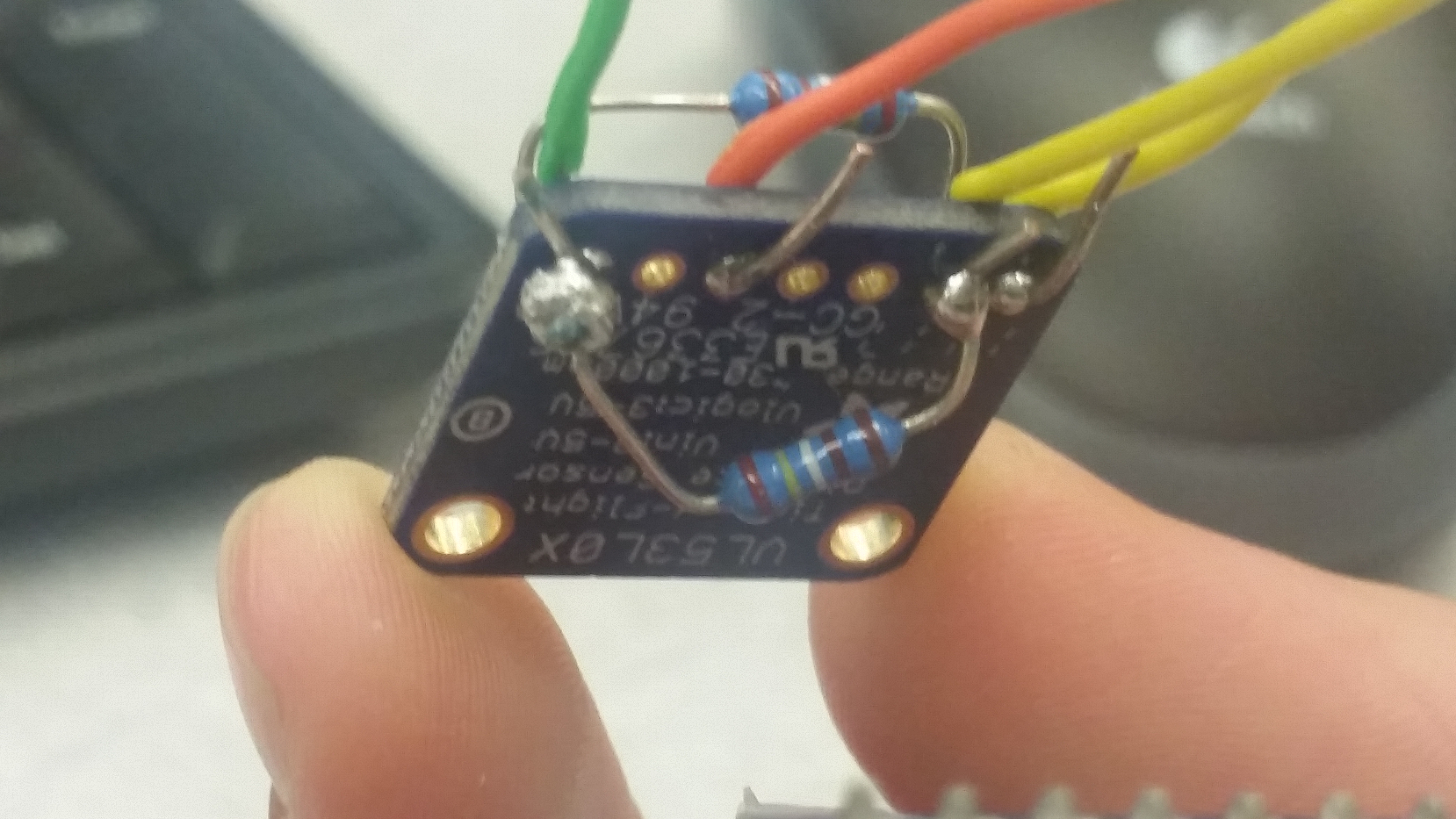
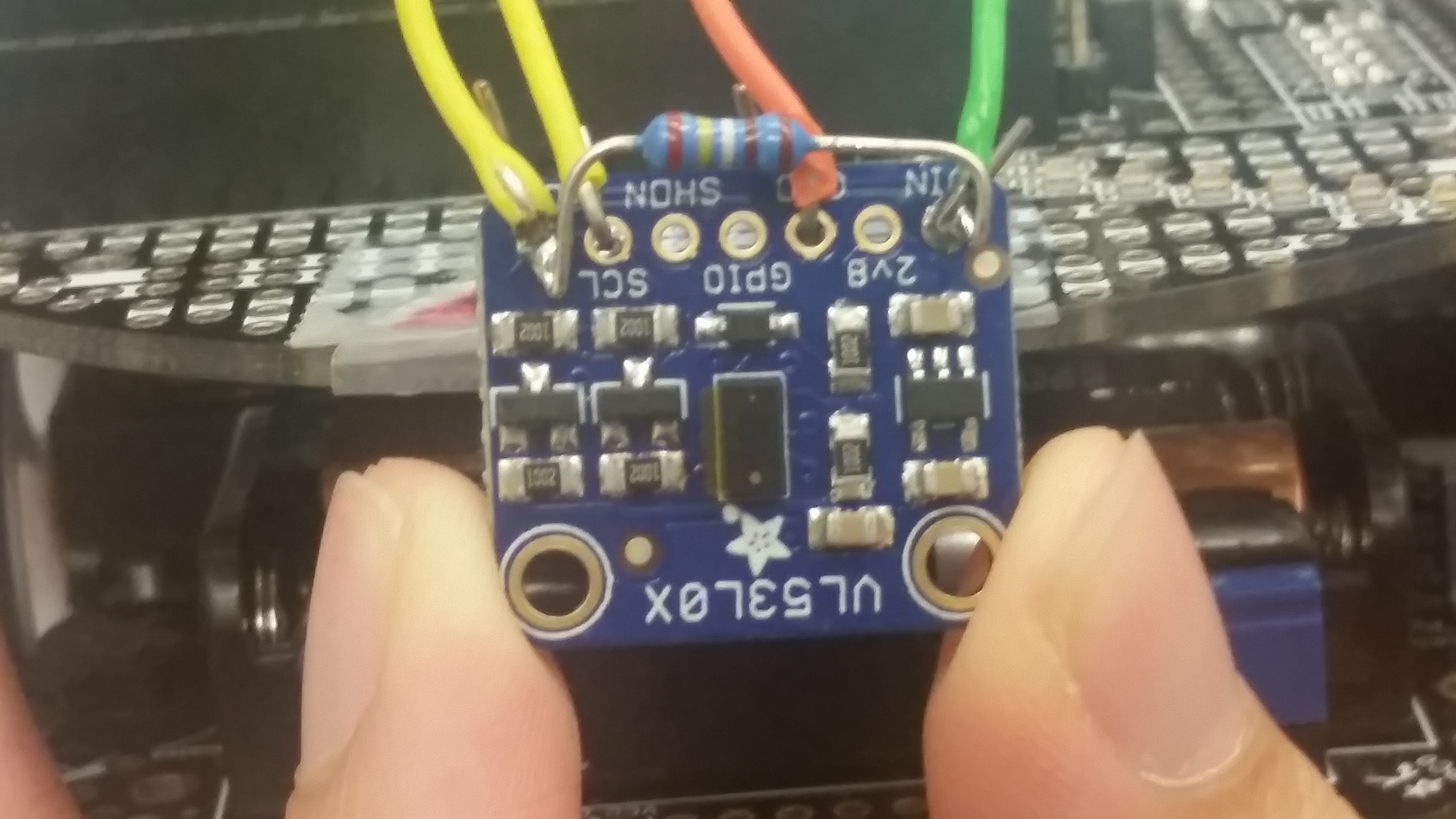
We used the Adafruit VL53L0X Time of FLight Micro-LIDAR Distance Breakout for our LIDAR sensor. It's connected to the Mbed via I2C pins. We also have a 2.2 KOhms resistor soldered on the LIDAR sensor from VIN to SDA and another from VIN to SDI.
| Mbed | VL53L0X |
|---|---|
| p28 | VL53L0X_SDA |
| p27 | VL53L0X_SCL |
| VU | VIN |
| GND | GND |
Wiring for the LIDAR sensor to the mbed
Import programHelloWorld_53L0A1
Simple HelloWorld program for the VL53L0X LIDAR sensor.
Here's some video demos of the m3pi robot using the LIDAR sensor to detect obstacles.
Import programm3pi_LIDAR
An m3pi demo program utilizing a LIDAR sensor.
Bluetooth & Solenoid Ping Pong Launcher
We used a HM-10 CC2540 CC2541 BLE Bluetooth 4.0 Serial Wireless Module Arduino as our bluetooth chip to control the robot via bluetooth. A link to the HM10 wiki can be found here.
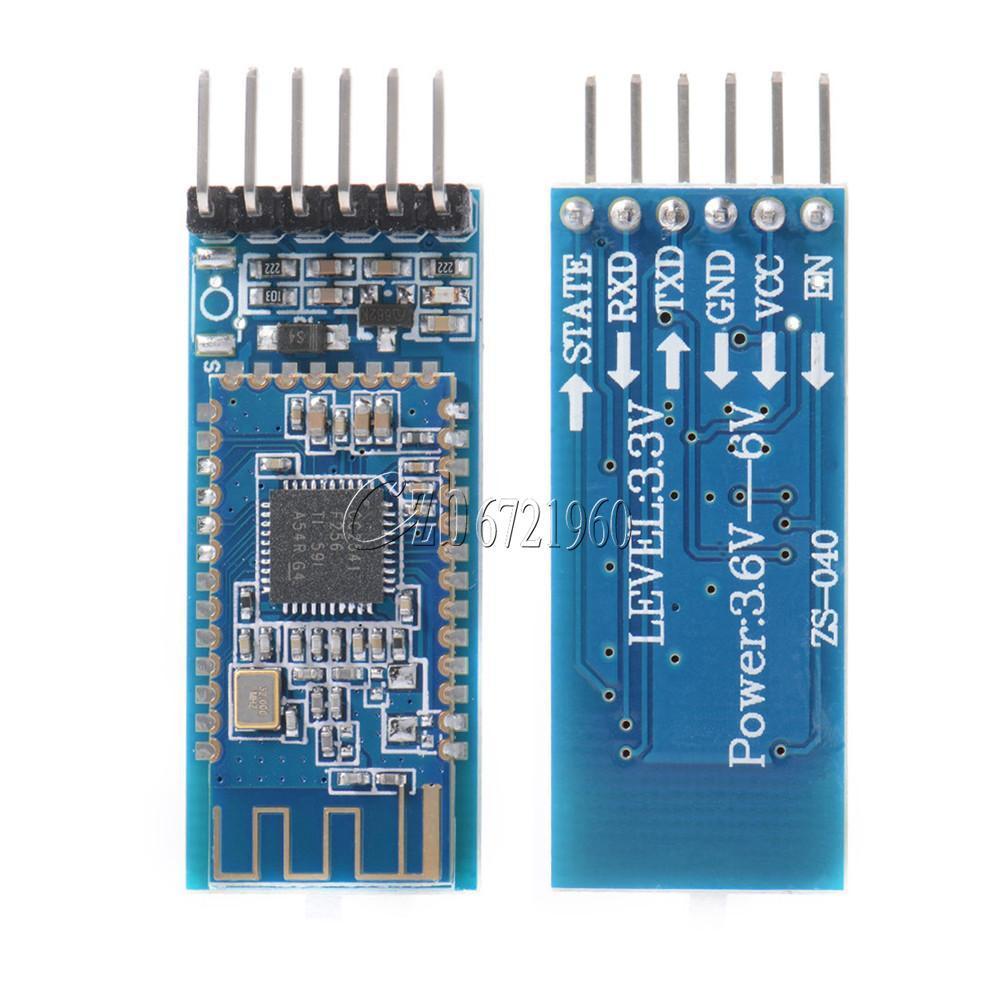
We used two HM10's on two separate mbeds. We configured the one attached to the robot as a slave node and the other one was the master. Once the slave node is configured it will stay a slave node until it is reset regardless of the power turning off. The code for the master has the device search for slave nodes. When it finds one it will connect and start sending commands. The mbed connected to the master node receives serial commands from the GUI. The master node then sends the commands to the mbed attached to the slave node. The code to configure a slave node is shown below along with the code running on the master node.
HM10 Slave
#include "mbed.h"

Serial hm10(p13,p14); //TX, RX
Serial pc(USBTX, USBRX);

int main()
{
    while(!hm10.writeable()) {} //wait until writeable

    pc.printf("\r\nStarting Slave Program\r\n");
    hm10.printf("AT+RENEW\r\n");
    pc.printf("Device Reset\r\n");
    wait(2);
    hm10.printf("AT+ROLE0\r\n"); //set chip to slave mode
    pc.printf("Device Set to Slave\r\n");

}
HM10 Master
#include "mbed.h"

// set up the HM10 Serial connection
Serial hm10(p13, p14); //TX, RX
Serial pc(USBTX, USBRX);

int main()
{
    char buffer[10];
    while(!hm10.writeable()) {} //wait until writeable

    pc.printf("\r\nStarting Master Program\r\n");
    hm10.printf("AT+RENEW\r\n");
    pc.printf("Device Reset\r\n");
    wait(2);
    hm10.printf("AT+ROLE1\r\n");
    pc.printf("Device Set to Master\r\n");

    while (hm10.readable()) //flush hm10 buffer
        pc.putc(hm10.getc());

    wait(2);
    hm10.printf("AT+INQ\r\n"); //inquires if there are any slaves nearby
    pc.printf("Device Looking for Slaves\r\n");

    int numDevices = -1;

    while (numDevices <= 0) {
        if (hm10.getc() == 'D') { //waits for "Devices Found x" line
            for (int i = 0; i < 13; i++) //skip to number of devices
                char temp = hm10.getc();

            numDevices = hm10.getc() - '0';
            pc.printf("Found %i Slave Devices \r\n", numDevices);
            if (numDevices == 0)
                hm10.printf("AT+INQ\r\n");
        }
    }
    pc.printf("Connecting to device 1\r\n");
    hm10.printf("AT+CONN1\r\n"); //connects to first device in the list
    wait(3); //wait to connect

    pc.printf("Sending GUI Commands\r\n");
    while(1) { //Send instructions to slave to turn on LEDs
        while (hm10.readable()) {
            pc.putc(hm10.getc());
        }
        if (hm10.writeable()) {
            //////
            pc.gets(buffer, 3);
            hm10.printf("%s", buffer);
        }
    }
}
Below is the code that is loaded onto the mbed with the slave node after it's been configured.
Robot Movement Code
#include "mbed.h"
#include "m3pi.h"

m3pi m3pi;
DigitalOut led(LED1);
DigitalOut pong(p20);
Serial bt(p13, p14); //TX, RX

int main()
{
    m3pi.locate(0,1);
    m3pi.printf("YO");

    while (!bt.readable()) { } //wait until the bt is ready

///////LED change will register if the command was recieved or not
    while(1) {

        if (bt.getc()=='F') {
            m3pi.forward(.25);
            led = !led;
        }
        if (bt.getc()=='B') {
            m3pi.backward(.25);
            led = !led;
        }
        if (bt.getc()=='L') {
            m3pi.left(.25);
            led = !led;
        }
        if (bt.getc()=='R') {
            m3pi.right(.25);
            led = !led;
        }
        if (bt.getc()=='S') {
            m3pi.stop();
            led = !led;
        }
        if (bt.getc()=='X') {
            pong = 1;
            led = !led;
            wait(.001);
            pong = 0;
        }
        while (bt.readable()) char temp = bt.getc(); //flush buffer
    }
}
| Mbed | HM10 |
|---|---|
| p13 | RXD |
| p14 | TXD |
| VOUT | VCC |
| GND | GND |
Wiring for the HM10
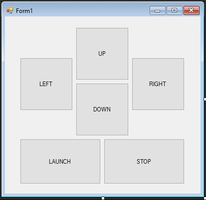
GUI Front Panel
Below are pictures of the solenoid ping pong launcher
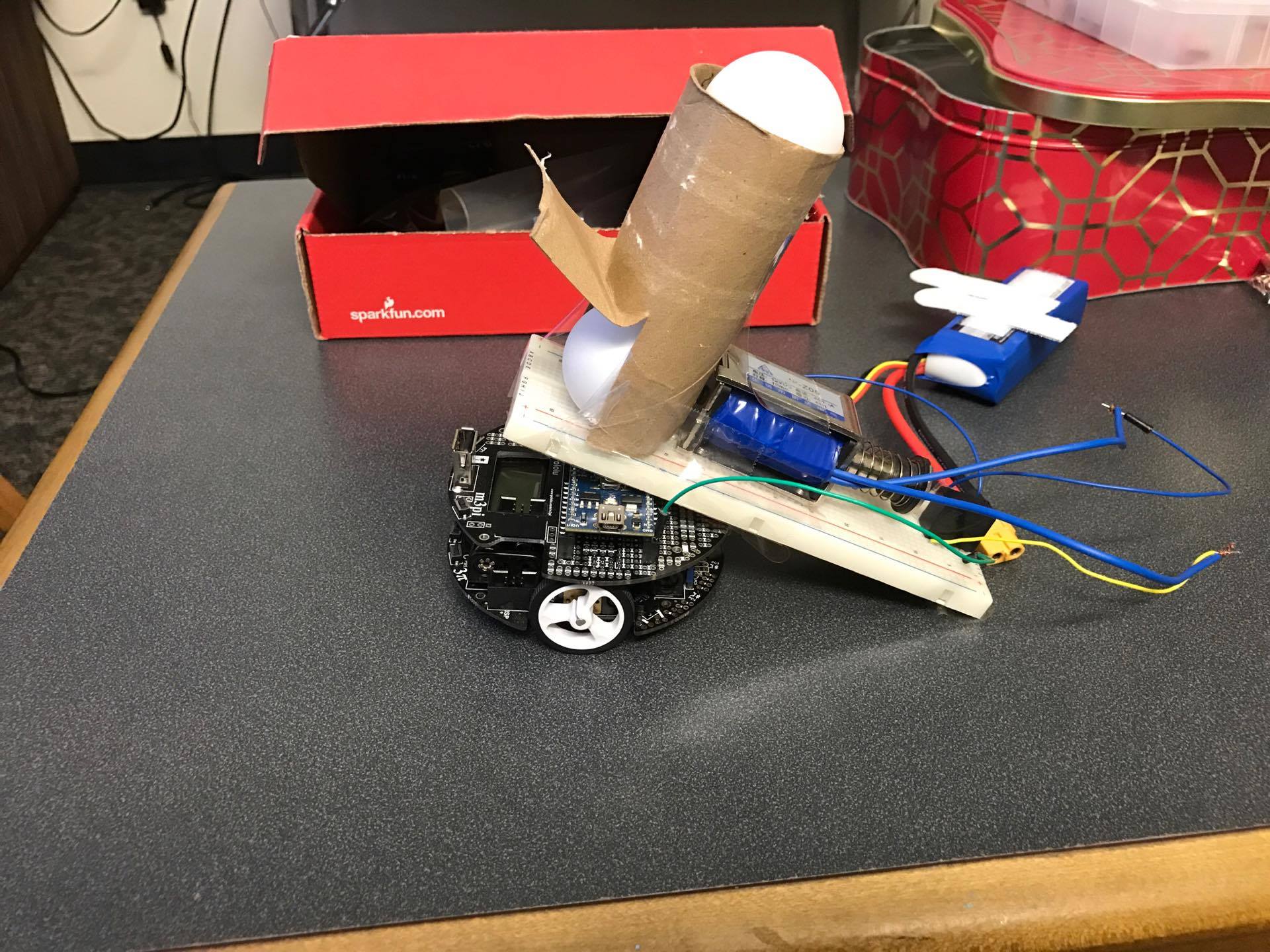
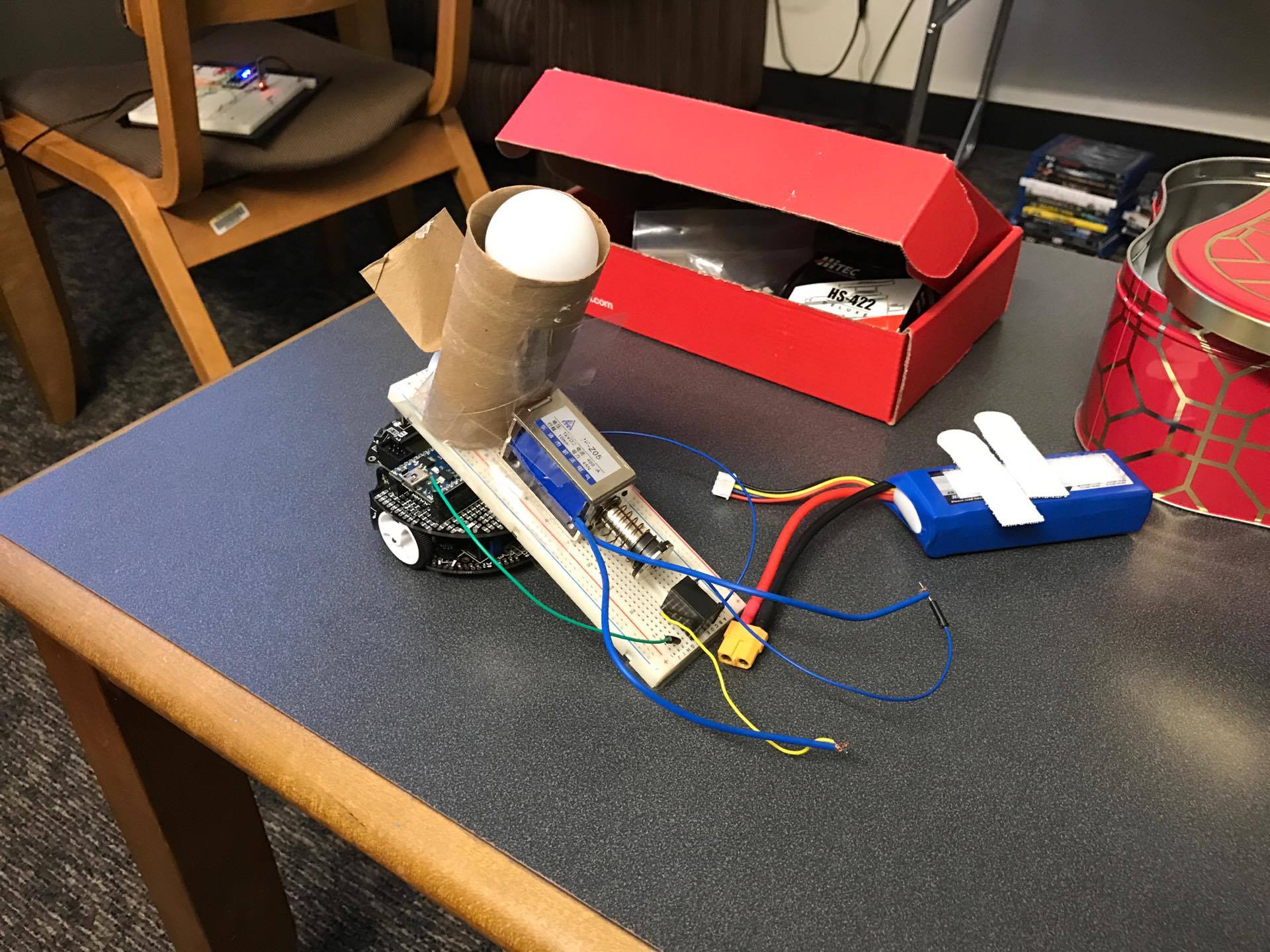
Below are demo's of the robot being controlled by bluetooth.
Import programm3pi_BT
An m3pi demo program for Bluetooth control.
Please log in to post comments.
