Important changes to repositories hosted on mbed.com
Mbed hosted mercurial repositories are deprecated and are due to be permanently deleted in July 2026.
To keep a copy of this software download the repository Zip archive or clone locally using Mercurial.
It is also possible to export all your personal repositories from the account settings page.
Dependencies: C12832_lcd DebounceIn mbed
You are viewing an older revision! See the latest version
Homepage


Introduction:
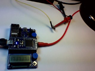
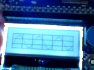
The MBED Oscilloscope uses the Analog Input on pin 17 to display connected waveforms from another MBED or a function generator. Note that the above left photo shows the Ain 1/8" phone jack on the side of the MBED being used as the input for a function generator. The crude photo on the right shows the waveform displayed on the MBED LCD screen (this is using the Application board available to plug the MBED processor board into. It includes the LCD screen as well as buttons, pots, temperature sensor, wifly socket, speaker, etc).
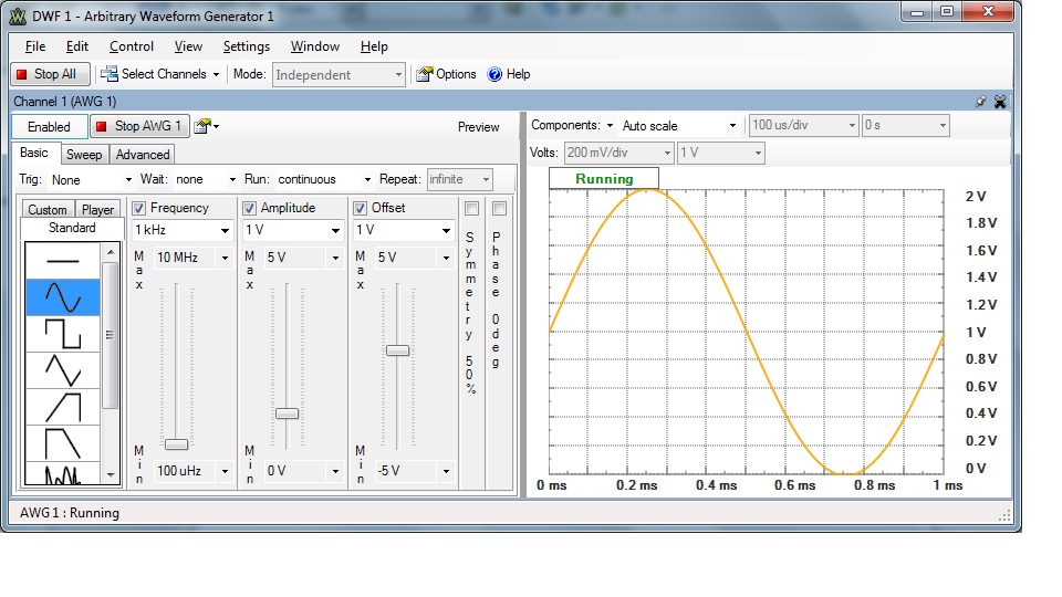
The waveform that is displayed on the MBED Oscilloscope is:  This is from a Digilent combination function generator, Oscilloscope, and logic analyzer. The arbitrary waveform generator shown is one of the features of the unit and allows output of several types of signals from its analog output.
Notice that the frequency is set to 1kHz. The MBED Oscilloscope is set to 512 uS per division (due to display limitations, the settings cannot be displayed with the waveform). The displayed waveform shows a complete period in approximately 2 divisions. The scope is indicating that the period is 1mS or 1kHz.
Capabilities and Limitations:
The scope can display waveforms up to 5kHz with some clarity (although 5kHz is pushing its resolution - 23kHz is a good practical limit). For displaying waveforms from a function generator running on another MBED, this is not a significant limitation. Except for the square-wave function, the function generator output of the MBED is around 1kHz realistically (the square-wave can output much higher frequencies since it only has two levels). (NOTE: this limitation is not strictly due to the ADC input. it also has to do with loop delay i.e. display update times...etc)
When an input is configured as an Analog input to the ADC, it is not 5V tolerant. The voltage on the pin must not exceed the reference-voltage-plus (set to approx 3V on the MBED board). So the amplitude input is limited to 3V (Although I've input signals at 3.3V with no immediate issues). Again this is not a significant limitation if debugging signals from another MBED. However, if you are using an external function generator, you must ensure you do not overdrive the input.
Usage:
Using the scope is fairly straight forward. Once you have the waveform source connected to pin 17 (either via the 1/8" phone jack or a wire directly connected to p17 through the header), the waveform should be displayed.
To change the time-base, use the right and left joystick buttons. You can check the current setting by pressing the middle button of the joystick. As long as you keep the middle button pressed, the settings page will be displayed. It shows the current