Using the Analog in and LCD, turn the MBED into a simple Oscilloscope
Dependencies: C12832_lcd DebounceIn mbed
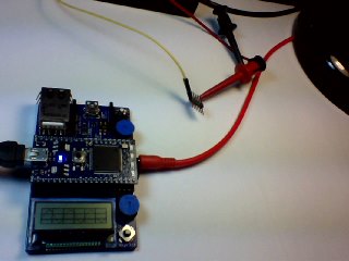
Introduction:
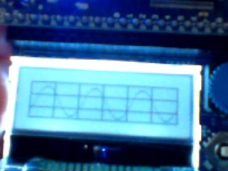
The MBED Oscilloscope uses the Analog Input on pin 17 to display connected waveforms from another MBED or a function generator. Note that the above left photo shows the Ain 1/8" phone jack on the side of the MBED being used as the input for a function generator. The crude photo on the right shows the waveform displayed on the MBED LCD screen (this is using the Application board available to plug the MBED processor board into. It includes the LCD screen as well as buttons, pots, temperature sensor, wifly socket, speaker, etc).
The waveform that is displayed on the MBED Oscilloscope is: 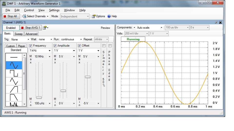 This is from a Digilent combination function generator, Oscilloscope, and logic analyzer. The arbitrary waveform generator shown is one of the features of the unit and allows output of several types of signals from its analog output.
Notice that the frequency is set to 1kHz. The MBED Oscilloscope is set to 512 uS per division (due to display limitations, the settings cannot be displayed with the waveform). The displayed waveform shows a complete period in approximately 2 divisions. The scope is indicating that the period is 1mS or 1kHz.
Capabilities and Limitations:
The scope can display waveforms up to 5kHz with some clarity (although 5kHz is pushing its resolution 2-3kHz is a good practical limit). For displaying waveforms from a function generator running on another MBED, this is not a significant limitation. Except for the square-wave function, the function generator output of the MBED is around 1kHz realistically (the square-wave can output much higher frequencies since it only has two levels). (NOTE: this limitation is not strictly due to the ADC input. it also has to do with loop delay i.e. display update times...etc)
When an input is configured as an Analog input to the ADC, it is not 5V tolerant. The voltage on the pin must not exceed the reference-voltage-plus (set to approx 3V on the MBED board). So the amplitude input is limited to 3V (Although I've input signals at 3.3V with no immediate issues). Again this is not a significant limitation if debugging signals from another MBED. However, if you are using an external function generator, you must ensure you do not overdrive the input.
Usage:
Using the scope is fairly straight forward. Once you have the waveform source connected to pin 17 (either via the 1/8" phone jack or a wire directly connected to p17 through the header), the waveform should be displayed.
To change the time-base, use the right and left joystick buttons. You can check the current setting by pressing the middle button of the joystick. As long as you keep the middle button pressed, the settings page will be displayed. It shows the current settings of the time-base, vertical or volt-base, and the trigger mode. The photo below shows the settings page:
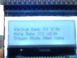
Again, I apologize for the crudeness of the photo (a photographer I am not). Note that the time-base will change based on whether the grid is turned on. In the first photo above you see the grid lines painted on the display. You have the option to turn those off and there are instances where it is desirable. When this is done, the entire horizontal screen is viewed as one division. So the time-base will change accordingly.
Once you release the center button, the display will return to the waveform screen after about a second. If however you press the center button again within that window, you will be taken to the trigger selection window:
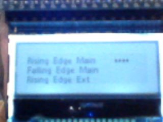
There are five trigger modes:
1. Rising-Edge Main Signal (this finds the rising edge on the signal connected to pin 17)
2. Falling-Edge Main Signal (Same as above but finds the falling edge)
3. Rising-Edge Ext Signal (this finds the rising edge on the signal connected to pin 18)
4. Falling-Edge Ext Signal (Sam as in 3 for falling edge)
5. Auto or No Trigger (this does not look for a trigger - useful for dc signals)
Note that only three modes are displayed on the screen. The screen will scroll as you move the selection down. This is done with the "up" and "down" buttons on the joystick. Make your selection by pressing the center button again.
Once you make your trigger selection, you will then be taken to the grid selection menu:
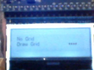
This allows the choice of whether to display the grid. Again there are situations you may want to disable the grid. Make the grid selection in the same way by pressing the center button of the joystick.
Once this selection is made, you will return the the waveform display.
The only additional control it connected to pot2. This is the pot furthest from the display. It controls the trigger level.
Know Issues:
1. The External triggering is not working at all right now. For some reason having two active signals connected to two different ADC inputs causes crosstalk that distorts both signals. I haven't looked into this yet so avoid using external triggering for the present. I will update when and if it is fixed. (any input or pointers would be appreciated)
2. The time base needs to be calibrated a little better. It is pretty close in most cases and good enough for rough work, but you would not want to keep time with it. It is a little like whack-a-mole and may never be perfect, but it can be improved.
3. The timeouts for the triggering mechanism may need some tweaking at some point as well. I think it is pretty good but may cause some fringe problems.
4. The trigger level is not currently displayed anywhere and should be part of the settings page. This would need to be added to a second settings page (and the menu system might get cumbersome at some point).
5. The pot is a little jittery for the trigger level. However, adding another menu to set it with the joystick will further push the problem in 4 of the menu system getting cumbersome. It may be good enough with some tweaks.
Future enhancements:
1. Getting the external triggering working is the first order of business.
2. Getting the time-base closer to reality will make things nicer.
3. I believe the grid would be nicer if the lines were dotted.
4. A classmate suggested adding FFT capabilities for a limited spectrum analyzer.
Any other suggestions?
Accessories:
I put together some faux scope probes by purchasing an inexpensive 3-foot audio cable (it is not shielded as the frequencies we are dealing with are fairly low). I cut this in half and soldered on some clips to connect the center and ground connections for the Ain 1/8" phone jack. The cable I got was actually stereo and I used a DMM to find which bare-wire was connected to pin 17 on the MBED. This accessory does make it nice in most cases.
However you can achieve the same results by connecting two wires directly one to pin 17 and the other to GND on the header connections of the application board directly to the input signal and GND of your waveform output.
main.cpp@0:9ccc4b6355a8, 2014-05-24 (annotated)
- Committer:
- trichards1138
- Date:
- Sat May 24 05:13:25 2014 +0000
- Revision:
- 0:9ccc4b6355a8
- Child:
- 1:4080ce288aea
First commit for Oscilloscope
Who changed what in which revision?
| User | Revision | Line number | New contents of line |
|---|---|---|---|
| trichards1138 | 0:9ccc4b6355a8 | 1 | #include "mbed.h" |
| trichards1138 | 0:9ccc4b6355a8 | 2 | #include "C12832_lcd.h" |
| trichards1138 | 0:9ccc4b6355a8 | 3 | //#include "DebounceIn.h" |
| trichards1138 | 0:9ccc4b6355a8 | 4 | #include "rtos.h" |
| trichards1138 | 0:9ccc4b6355a8 | 5 | |
| trichards1138 | 0:9ccc4b6355a8 | 6 | Serial pc(USBTX, USBRX); |
| trichards1138 | 0:9ccc4b6355a8 | 7 | C12832_LCD LCD; |
| trichards1138 | 0:9ccc4b6355a8 | 8 | AnalogIn Ain(p17); |
| trichards1138 | 0:9ccc4b6355a8 | 9 | AnalogOut Aout(p18); |
| trichards1138 | 0:9ccc4b6355a8 | 10 | AnalogIn pot1(p19); |
| trichards1138 | 0:9ccc4b6355a8 | 11 | AnalogIn pot2(p20); |
| trichards1138 | 0:9ccc4b6355a8 | 12 | DigitalIn up(p15); |
| trichards1138 | 0:9ccc4b6355a8 | 13 | DigitalIn down(p12); |
| trichards1138 | 0:9ccc4b6355a8 | 14 | DigitalIn left(p13); |
| trichards1138 | 0:9ccc4b6355a8 | 15 | DigitalIn right(p16); |
| trichards1138 | 0:9ccc4b6355a8 | 16 | BusIn joy(p15,p12,p13,p16); |
| trichards1138 | 0:9ccc4b6355a8 | 17 | DigitalIn update(p14); |
| trichards1138 | 0:9ccc4b6355a8 | 18 | PwmOut testout(p21); |
| trichards1138 | 0:9ccc4b6355a8 | 19 | PwmOut tled(LED1); |
| trichards1138 | 0:9ccc4b6355a8 | 20 | /* |
| trichards1138 | 0:9ccc4b6355a8 | 21 | DebounceIn OnOff(p14); |
| trichards1138 | 0:9ccc4b6355a8 | 22 | DebounceIn up(p15); |
| trichards1138 | 0:9ccc4b6355a8 | 23 | DebounceIn down(p12); |
| trichards1138 | 0:9ccc4b6355a8 | 24 | DebounceIn left(p13); |
| trichards1138 | 0:9ccc4b6355a8 | 25 | DebounceIn right(p16); |
| trichards1138 | 0:9ccc4b6355a8 | 26 | */ |
| trichards1138 | 0:9ccc4b6355a8 | 27 | |
| trichards1138 | 0:9ccc4b6355a8 | 28 | float time_base = 0.1; |
| trichards1138 | 0:9ccc4b6355a8 | 29 | float volt_base = 3.0; |
| trichards1138 | 0:9ccc4b6355a8 | 30 | float trigger = 1.0; |
| trichards1138 | 0:9ccc4b6355a8 | 31 | |
| trichards1138 | 0:9ccc4b6355a8 | 32 | // Thread flatdc - called if user selects dc sig |
| trichards1138 | 0:9ccc4b6355a8 | 33 | // pot2 controls the height of dc signal |
| trichards1138 | 0:9ccc4b6355a8 | 34 | void flatdc(const void *arg) |
| trichards1138 | 0:9ccc4b6355a8 | 35 | { |
| trichards1138 | 0:9ccc4b6355a8 | 36 | while(true) { // thread loop |
| trichards1138 | 0:9ccc4b6355a8 | 37 | Aout.write(pot2.read()); // scale the height of wave |
| trichards1138 | 0:9ccc4b6355a8 | 38 | Thread::wait(1000); |
| trichards1138 | 0:9ccc4b6355a8 | 39 | } |
| trichards1138 | 0:9ccc4b6355a8 | 40 | } |
| trichards1138 | 0:9ccc4b6355a8 | 41 | |
| trichards1138 | 0:9ccc4b6355a8 | 42 | #define VBASEMAX 8 |
| trichards1138 | 0:9ccc4b6355a8 | 43 | #define TBASEMAX 7 |
| trichards1138 | 0:9ccc4b6355a8 | 44 | void update_params(void) |
| trichards1138 | 0:9ccc4b6355a8 | 45 | { |
| trichards1138 | 0:9ccc4b6355a8 | 46 | float next_tbase[] = { 0.001, 0.01, 0.1, 1.0, 10.0, 100.0, 1000.0 }; |
| trichards1138 | 0:9ccc4b6355a8 | 47 | float next_vbase[] = { 3.0, 2.5, 2.0, 1.5, 1.0, 0.5, 0.25, 0.125 }; |
| trichards1138 | 0:9ccc4b6355a8 | 48 | int vsel=0, tsel=1; |
| trichards1138 | 0:9ccc4b6355a8 | 49 | /* |
| trichards1138 | 0:9ccc4b6355a8 | 50 | LCD.locate(0,3); |
| trichards1138 | 0:9ccc4b6355a8 | 51 | LCD.printf("Set the Trigger Level: %f", trigger); |
| trichards1138 | 0:9ccc4b6355a8 | 52 | LCD.locate(0,13); |
| trichards1138 | 0:9ccc4b6355a8 | 53 | LCD.printf("Set the Time Base: %f", time_base); |
| trichards1138 | 0:9ccc4b6355a8 | 54 | */ |
| trichards1138 | 0:9ccc4b6355a8 | 55 | if( up ) { |
| trichards1138 | 0:9ccc4b6355a8 | 56 | volt_base = next_vbase[vsel++]; |
| trichards1138 | 0:9ccc4b6355a8 | 57 | if( vsel == VBASEMAX ) |
| trichards1138 | 0:9ccc4b6355a8 | 58 | vsel = 0; |
| trichards1138 | 0:9ccc4b6355a8 | 59 | // LCD.locate(16,27); |
| trichards1138 | 0:9ccc4b6355a8 | 60 | //LCD.set_font((unsigned char*) Small_7); |
| trichards1138 | 0:9ccc4b6355a8 | 61 | //LCD.printf("v base: %f", volt_base); |
| trichards1138 | 0:9ccc4b6355a8 | 62 | } |
| trichards1138 | 0:9ccc4b6355a8 | 63 | if( down ) { |
| trichards1138 | 0:9ccc4b6355a8 | 64 | volt_base = next_vbase[vsel--]; |
| trichards1138 | 0:9ccc4b6355a8 | 65 | if( vsel == -1 ) |
| trichards1138 | 0:9ccc4b6355a8 | 66 | vsel = VBASEMAX-1; |
| trichards1138 | 0:9ccc4b6355a8 | 67 | //LCD.locate(16,27); |
| trichards1138 | 0:9ccc4b6355a8 | 68 | //LCD.set_font((unsigned char*) Small_7); |
| trichards1138 | 0:9ccc4b6355a8 | 69 | //LCD.printf("v base: %f", volt_base); |
| trichards1138 | 0:9ccc4b6355a8 | 70 | } |
| trichards1138 | 0:9ccc4b6355a8 | 71 | if( right ) { |
| trichards1138 | 0:9ccc4b6355a8 | 72 | time_base = next_tbase[tsel++]; |
| trichards1138 | 0:9ccc4b6355a8 | 73 | if( tsel == TBASEMAX ) |
| trichards1138 | 0:9ccc4b6355a8 | 74 | tsel = 0; |
| trichards1138 | 0:9ccc4b6355a8 | 75 | //LCD.locate(0,27); |
| trichards1138 | 0:9ccc4b6355a8 | 76 | //LCD.set_font((unsigned char*) Small_7); |
| trichards1138 | 0:9ccc4b6355a8 | 77 | //LCD.printf("t base: %f", time_base); |
| trichards1138 | 0:9ccc4b6355a8 | 78 | } |
| trichards1138 | 0:9ccc4b6355a8 | 79 | if( left ) { |
| trichards1138 | 0:9ccc4b6355a8 | 80 | time_base = next_tbase[tsel--]; |
| trichards1138 | 0:9ccc4b6355a8 | 81 | if( tsel == -1 ) |
| trichards1138 | 0:9ccc4b6355a8 | 82 | tsel = TBASEMAX-1; |
| trichards1138 | 0:9ccc4b6355a8 | 83 | //LCD.locate(0,27); |
| trichards1138 | 0:9ccc4b6355a8 | 84 | //LCD.set_font((unsigned char*) Small_7); |
| trichards1138 | 0:9ccc4b6355a8 | 85 | //LCD.printf("t base: %f", time_base); |
| trichards1138 | 0:9ccc4b6355a8 | 86 | } |
| trichards1138 | 0:9ccc4b6355a8 | 87 | } |
| trichards1138 | 0:9ccc4b6355a8 | 88 | |
| trichards1138 | 0:9ccc4b6355a8 | 89 | |
| trichards1138 | 0:9ccc4b6355a8 | 90 | // float time_base = next_tbase[1]; |
| trichards1138 | 0:9ccc4b6355a8 | 91 | // float volt_base = next_vbase[0]; |
| trichards1138 | 0:9ccc4b6355a8 | 92 | // float trigger = 1.0; |
| trichards1138 | 0:9ccc4b6355a8 | 93 | void displayWave(const void *arg) |
| trichards1138 | 0:9ccc4b6355a8 | 94 | { |
| trichards1138 | 0:9ccc4b6355a8 | 95 | unsigned int i; |
| trichards1138 | 0:9ccc4b6355a8 | 96 | unsigned int h = LCD.height()-2, w = LCD.width(), hhh; |
| trichards1138 | 0:9ccc4b6355a8 | 97 | while(true) { // thread loop |
| trichards1138 | 0:9ccc4b6355a8 | 98 | for (i=0; i<w; i++) { |
| trichards1138 | 0:9ccc4b6355a8 | 99 | hhh = (int)((h+1)-(h*Ain.read())); |
| trichards1138 | 0:9ccc4b6355a8 | 100 | LCD.pixel(i, hhh ,1); // print pixel |
| trichards1138 | 0:9ccc4b6355a8 | 101 | Thread::wait(time_base); |
| trichards1138 | 0:9ccc4b6355a8 | 102 | } |
| trichards1138 | 0:9ccc4b6355a8 | 103 | LCD.copy_to_lcd(); // LCD.pixel does not update the lcd |
| trichards1138 | 0:9ccc4b6355a8 | 104 | Thread::wait(20); |
| trichards1138 | 0:9ccc4b6355a8 | 105 | LCD.cls(); |
| trichards1138 | 0:9ccc4b6355a8 | 106 | /* pc.printf("1"); |
| trichards1138 | 0:9ccc4b6355a8 | 107 | if( up ) { //|| down || left || right ) { //update ) { |
| trichards1138 | 0:9ccc4b6355a8 | 108 | pc.printf("I'm updating Parameters\r\n"); |
| trichards1138 | 0:9ccc4b6355a8 | 109 | update_params(); |
| trichards1138 | 0:9ccc4b6355a8 | 110 | LCD.cls(); |
| trichards1138 | 0:9ccc4b6355a8 | 111 | } |
| trichards1138 | 0:9ccc4b6355a8 | 112 | */ |
| trichards1138 | 0:9ccc4b6355a8 | 113 | // pc.printf("2"); |
| trichards1138 | 0:9ccc4b6355a8 | 114 | LCD.rect(0,0,w,h+2,1); |
| trichards1138 | 0:9ccc4b6355a8 | 115 | while( Ain.read() < 0.2 ) |
| trichards1138 | 0:9ccc4b6355a8 | 116 | Thread::wait(time_base); |
| trichards1138 | 0:9ccc4b6355a8 | 117 | } |
| trichards1138 | 0:9ccc4b6355a8 | 118 | } |
| trichards1138 | 0:9ccc4b6355a8 | 119 | |
| trichards1138 | 0:9ccc4b6355a8 | 120 | |
| trichards1138 | 0:9ccc4b6355a8 | 121 | int main() |
| trichards1138 | 0:9ccc4b6355a8 | 122 | { |
| trichards1138 | 0:9ccc4b6355a8 | 123 | pc.baud(19200); |
| trichards1138 | 0:9ccc4b6355a8 | 124 | |
| trichards1138 | 0:9ccc4b6355a8 | 125 | testout.period_us(1000); |
| trichards1138 | 0:9ccc4b6355a8 | 126 | testout.pulsewidth_us(500); |
| trichards1138 | 0:9ccc4b6355a8 | 127 | |
| trichards1138 | 0:9ccc4b6355a8 | 128 | Thread display(displayWave); |
| trichards1138 | 0:9ccc4b6355a8 | 129 | // Thread dc(flatdc); |
| trichards1138 | 0:9ccc4b6355a8 | 130 | |
| trichards1138 | 0:9ccc4b6355a8 | 131 | while(1) { |
| trichards1138 | 0:9ccc4b6355a8 | 132 | testout.pulsewidth_us(pot2.read_u16()); |
| trichards1138 | 0:9ccc4b6355a8 | 133 | Thread::wait(1000); |
| trichards1138 | 0:9ccc4b6355a8 | 134 | } |
| trichards1138 | 0:9ccc4b6355a8 | 135 | |
| trichards1138 | 0:9ccc4b6355a8 | 136 | } |
| trichards1138 | 0:9ccc4b6355a8 | 137 |