SOLDADOR DE DOBLE PULSO CON BLUEPILL STM32F103
Dependencies: mbed QEI Debounced TextLCD
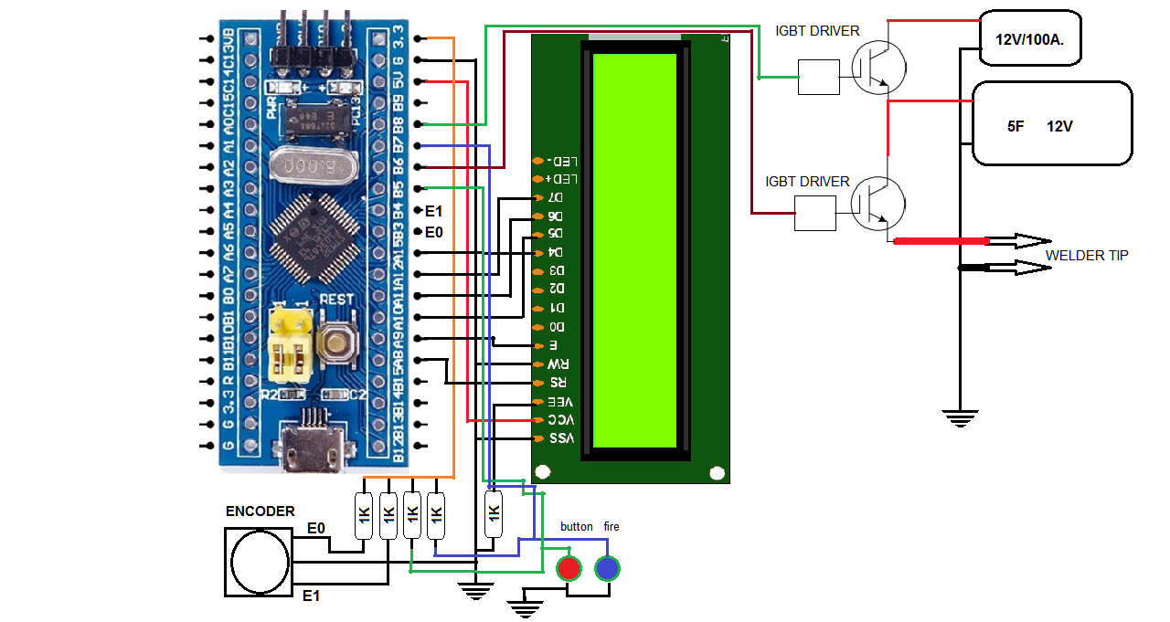
SOLDADOR DE PUNTO PARA SOLDAR BATERIAS DE IONES DE LITIO CON LAMINAS DE NICKEL. EMPLEA UN STM32F103 BLUEPILL. CON UN ENCODER ROTATORIO SE CONFIGURAN TRES TIEMPOS PARA LOS DOS PULSOS Y UN PERIODO DE ESPERA. EL PROGRAMA INICIA CON LA CARGA DEL CONDENSADOR (IGBT1)DE 5 FARADIOS Y TERMINADA LA CARGA DESCONECTA LA FUENTE DEL CONDENSADOR Y LUEGO ENVÍA EL DOBLE PULSO A LAS PUNTAS DEL SOLDADOR(IGBT). EL PULSO SE PUEDE REPETIR SOLO ACCIONANDO EL SUICHE DE PEDAL. (fire). UN PULSADOR ESTA INCORPORADO AL ENCODER (button) Y SIRVE PARA SELECCIONAR EL TIEMPO A CONFIGURAR. UNA VES LOS TIEMPOS SON LOS DESEADOS, SE PISA EL BOTON DE PIE (fire) Y LA SOLDADURA SE INICIA.
LOS tres TIEMPOS SE PUEDEN CAMBIAR ENTRE CERO Y 99 milisegundos

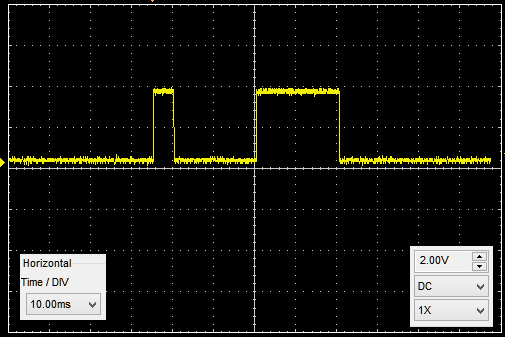
IMAGEN DE PRUEBA CON OSCILOSCOPIO
PULSO CORTO DE 5mS
DESCANSO Y PULSO LARGO 20mS

Diff: main.cpp
- Revision:
- 2:75153c8d2ef0
- Parent:
- 1:e10c603cf0ae
--- a/main.cpp	Tue Feb 05 14:00:02 2019 +0000
+++ b/main.cpp	Mon Apr 29 23:26:21 2019 +0000
@@ -1,60 +1,123 @@
-/* Hello World! for the TextLCD Enhanced Library*/
-
+//demo display y encoder
+//programa para probar un bluepill con encoder y lcd y pulsadores
+//control de soldador de punto de doble pulso
+//se emiten dos pulsos y una  espera intermedia
+//antes de hacer esto se carga un condensador de 5F por 3seg con  el IGBT1
+//luego se envian los pulsos de soldadura por el IGBT, con los tiempos configurados
 #include "mbed.h"
 #include "TextLCD.h"
-
-// Host PC Communication channels
-Serial  pc(PA_2, PA_3);     // tx, rx
+#include "QEI.h"

-// LCD instantiation
-TextLCD lcd(PA_8, PA_9, PA_10, PA_11, PA_12, PA_15, TextLCD::LCD16x2);  // 4-bit bus: RS, E, D4, D5, D6, D7
-Timer   t;
-
-int main()
-{
-    pc.printf("TextLCD Enhanced Test. Columns=%d, Rows=%d\n\r", lcd.columns(), lcd.rows());
+// se configura el lcd en este caso uno de cuatro filas
+TextLCD lcd(PA_8, PA_9, PA_10, PA_11, PA_12, PA_15, TextLCD::LCD16x4);  // 4-bit bus: RS, E, D4, D5, D6, D7

-    for (int row = 0; row < lcd.rows(); row++) {
-        int col = 0;
-
-        pc.printf("MemAddr(Col=%d, Row=%d)=0x%02X\n\r", col, row, lcd.getAddress(col, row));
-
-        lcd.putc('0' + row);
+int p=0,p1=0,p2=0,espera=0,pulsos=0;            //variables del programa
+int i=0;                          //posicion de la variable en el display
+QEI wheel (PB_3, PB_4, NC, 100);  //configuramos encoder de libreria. dos fases y pulsos x rev
+InterruptIn button(PB_5);
+DigitalIn fire(PB_7);  //boton pedal para soldar
+DigitalOut IGBT(PB_6); //señal para el igbt
+DigitalOut IGBT1(PB_8); //señal para el igbt1 de carga del condensador

-        for (col=1; col < lcd.columns() - 1; col++) {
-            lcd.putc('*');
-        }
-
-        pc.printf("MemAddr(Col=%d, Row=%d)=0x%02X\n\r", col, row, lcd.getAddress(col, row));
-        lcd.putc('+');
-    }
+void flip() {
+      wait_ms(100);
+      if(button==0){
+       i++;
+       if(i>2){
+           i=0;
+              }
+}
+}

-// Fill screen again and time it
-    t.start();
-
-    for (int row=0; row<lcd.rows(); row++) {
-        int col=0;
-
-        lcd.putc('0' + row);
-
-        for (col=1; col<lcd.columns()-1; col++) {
-            lcd.putc('*');
-        }
-
-        lcd.putc('+');
+void weld() {
+      if(fire==0){
+      IGBT1=1; // carga el condensador
+      wait(3); //tres segundos
+      IGBT1=0; //fin de la carga
+
+      IGBT=0;
+      wait_ms(10);
+      IGBT=1;
+      wait_ms(p1);
+      IGBT=0;
+      wait_ms(espera);
+      IGBT=1;
+      wait_ms(p2);
+      IGBT=0;
+      wait(3);
+}
+}
+
+//..............................INICIA EL PROGRAMA.......................................................
+int main()
+{
+//...............PANTALLA INICIAL...........................................
+inicio1:
+    button.fall(&flip);
+    IGBT1=0; //apaga el igbt de carga
+    lcd.cls();
+    lcd.locate(3,0);            //se posiciona en col 3 y fila 0
+    lcd.printf("SPOT WELDER");  //primer mensaje
+    lcd.locate(3,1);            //se posiciona en col 3 y fila 0
+    lcd.printf("DUAL PULSE");   //primer mensaje
+    wait(3);                    //espera 3 seg
+    lcd.cls();                  //borra pantalla
+    lcd.locate(0,0);            //se posiciona en col 8 y fila 0
+    lcd.printf("P1=");      //se marca una variable
+    lcd.locate(8,0);            //se posiciona 0,1
+    lcd.printf("P2=");      //se marca una variable
+    lcd.locate(0,1);            //se  posiciona en 8,1
+    lcd.printf("Esp=");       //se marca una variable
+    lcd.setCursor(TextLCD::CurOff_BlkOn);   //se configura el cursor LCD parpadeante.
+
+//..............................FIN PANTALLA INICIAL.....................................
+//.............programa ciclico..........................................................
+  while(1){
+
+if(i==0){
+lcd.locate(3,0);
+lcd.printf("  ");
+p1=wheel.getPulses();
+if(p1<0){
+    p1=0;
     }
-    t.stop();
-    pc.printf("All my hard work took %f sec\r\n", t.read());
+lcd.locate(3,0);
+lcd.printf("%d",p1);
+wait_ms(60);

-// Show cursor as blinking character
-    lcd.setCursor(TextLCD::CurOff_BlkOn);
+        }
+if(i==1){
+lcd.locate(11,0);
+lcd.printf("  ");
+p2=wheel.getPulses();
+if(p2<0){
+    p2=0;
+    }
+lcd.locate(11,0);
+lcd.printf("%d",p2);
+wait_ms(60);
+

-// Set and show user defined characters. A maximum of 8 UDCs are supported by the HD44780.
-// They are defined by a 5x7 bitpattern.
-    lcd.setUDC(0, (char *) udc_0);  // Show |>
-    lcd.putc(0);
-    lcd.setUDC(1, (char *) udc_1);  // Show <|
-    lcd.putc(1);
+        }
+if(i==2){
+lcd.locate(4,1);
+lcd.printf("  ");
+espera=wheel.getPulses();
+if(espera<0){
+    espera=0;
+    }
+lcd.locate(4,1);
+lcd.printf("%d",espera);
+wait_ms(60);

-    pc.printf("Bye now\r\n");
-}
+        }
+if(fire==0){
+    weld();
+/*  lcd.cls();
+    lcd.printf("WELD-OK");
+    wait(2);
+    goto inicio1;
+*/
+    }
+}//while
+}//main
\ No newline at end of file
 Gustavo Ramirez