This is a work in progress. Trying to make a working arcade button to USB interface with the Nucleo F411RE.
This project was inspired by USB Joystick Device
The goal of this project is to build an simple interface that I will connect numerous Arcade buttons and joysticks to the Nucleo board, and the Nucleo will present itself as a USB Gamepad to Windows or Linux. The joysticks are Arcade joysticks that have four switches, up/down/left/right. It is not an analog joystick, just a set of switches. These will be connected to the Nucleo's pins configured as inputs.
The code will then continuously loop and test which buttons are closed, and transfer this data to the host via USBGamepad protocol.
Much thanks to Wim Huiskamp for his original project, documentation, and later reaching out to me to guide me to solving a last minute problem. Wim clued me into the fact that I needed a 1k5 pullup resistor between the 3v3 pin and the PA_12/D+ pin. Once I did this Windows detected the device as a Gamepad and registered it correctly! Yay!
Connecting USB cable to the board is as follows:
You will need a USB data cable (the one I used had a micro usb on one end and regular usb on the other). I cut off the micro USB end, and cut the insulation back about 30mm. This exposed four wires, Red, Black, White and Green. You will then either crimp some header connectors or solder directly to the Nucleo header pins as follows:
- Green USB D+ to PA_12
- White USB D- to PA_11
- Red USB 5V to E5V (with jumper JP5 set to E5V)
- Black USB GND to GND
As an extra debugging measure, you can connect both the ST/Link USB and the PA_12/11 USB to the Windows machine to run both at the same time, and you can see printf messages from within ST/Link.
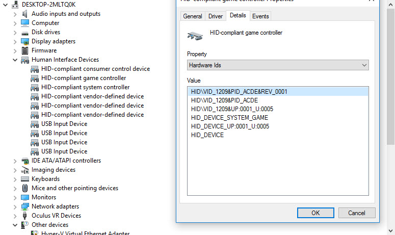
We can verify the HID Vendor and Product IDs by looking at the Device Manager, and look for the HID Game Controller:

I used pid.codes to register my own Vendor_ID and Product_ID
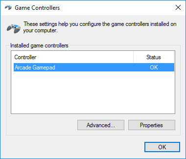
If you go to the USB Game Controller control panel widget, you will see the new entry for Arcade Gamepad:

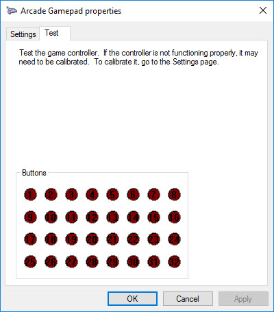
And here we can see all 32 buttons:

On the Nucleo board you may have difficulties depending on the revision. The board I am using is an STM32F411RE Revision C03, which has resistors and solder joints (bottom) to allow the use of the Crystal on the STLink board for USB purposes. After programming via STLink, remove the USB cable from the STLink, the jumper must be set to E5V to power the board from the PC's usb port. Plug the new cable into the PC.
When you're ready to install it in the arcade cabinet, or project, just remember to setup the jumper JP5 to E5V and you only need the single USB connection to the host.
Here are some useful links that I used to grasp all the little things involved in this project:
main.cpp
- Committer:
- thetazzbot
- Date:
- 2016-12-13
- Revision:
- 1:ad6066c16dbd
- Parent:
- 0:a743b4be0b04
- Child:
- 2:bdf03de86660
File content as of revision 1:ad6066c16dbd:
/* Modified for RetroPie MW 2016 */
/* Copyright 2014 M J Roberts, MIT License
*
* Permission is hereby granted, free of charge, to any person obtaining a copy of this software
* and associated documentation files (the "Software"), to deal in the Software without
* restriction, including without limitation the rights to use, copy, modify, merge, publish,
* distribute, sublicense, and/or sell copies of the Software, and to permit persons to whom the
* Software is furnished to do so, subject to the following conditions:
*
* The above copyright notice and this permission notice shall be included in all copies or
* substantial portions of the Software.
*
* THE SOFTWARE IS PROVIDED "AS IS", WITHOUT WARRANTY OF ANY KIND, EXPRESS OR IMPLIED, INCLUDING
* BUT NOT LIMITED TO THE WARRANTIES OF MERCHANTABILITY, FITNESS FOR A PARTICULAR PURPOSE AND
* NONINFRINGEMENT. IN NO EVENT SHALL THE AUTHORS OR COPYRIGHT HOLDERS BE LIABLE FOR ANY CLAIM,
* DAMAGES OR OTHER LIABILITY, WHETHER IN AN ACTION OF CONTRACT, TORT OR OTHERWISE, ARISING FROM,
* OUT OF OR IN CONNECTION WITH THE SOFTWARE OR THE USE OR OTHER DEALINGS IN THE SOFTWARE.
*/

//
//  - Button input wiring.  24 of the KL25Z's GPIO ports are mapped as digital inputs
//    for buttons and switches.  The software reports these as joystick buttons when
//    it sends reports to the PC.  These can be used to wire physical pinball-style
//    buttons in the cabinet (e.g., flipper buttons, the Start button) and miscellaneous
//    switches (such as a tilt bob) to the PC.  Visual Pinball can use joystick buttons
//    for input - you just have to assign a VP function to each button using VP's
//    keyboard options dialog.  To wire a button physically, connect one terminal of
//    the button switch to the KL25Z ground, and connect the other terminal to the
//    the GPIO port you wish to assign to the button.  See the buttonMap[] array
//    below for the available GPIO ports and their assigned joystick button numbers.
//    If you're not using a GPIO port, you can just leave it unconnected - the digital
//    inputs have built-in pull-up resistors, so an unconnected port is the same as
//    an open switch (an "off" state for the button).
//
//
// STATUS LIGHTS:  The on-board LED on the KL25Z flashes to indicate the current
// device status.  The flash patterns are:
//
//    two short red flashes = the device is powered but hasn't successfully
//        connected to the host via USB (either it's not physically connected
//        to the USB port, or there was a problem with the software handshake
//        with the USB device driver on the computer)
//
//    short red flash = the host computer is in sleep/suspend mode
//
//    long red/green = the LedWiz unti number has been changed, so a reset
//        is needed.  You can simply unplug the device and plug it back in,
//        or presss and hold the reset button on the device for a few seconds.
//
//    long yellow/green = everything's working, but the plunger hasn't
//        been calibrated; follow the calibration procedure described above.
//        This flash mode won't appear if the CCD has been disabled.  Note
//        that the device can't tell whether a CCD is physically attached;
//        if you don't have a CCD attached, you can set the appropriate option
//        in config.h or use the  Windows config tool to disable the CCD
//        software features.
//
//    alternating blue/green = everything's working
//
#include "mbed.h"
#include "math.h"
#include "USBJoystick.h"


#define DECL_EXTERNS
#include "config.h"


// ---------------------------------------------------------------------------
// utilities

// number of elements in an array
#define countof(x) (sizeof(x)/sizeof((x)[0]))

// floating point square of a number
inline float square(float x) { return x*x; }

// floating point rounding
inline float round(float x) { return x > 0 ? floor(x + 0.5) : ceil(x - 0.5); }


// --------------------------------------------------------------------------
//
// USB product version number
//
const uint16_t USB_VERSION_NO = 0x0007;


//
// Build the full USB product ID.  If we're using the LedWiz compatible
// vendor ID, the full product ID is the combination of the LedWiz base
// product ID (0x00F0) and the 0-based unit number (0-15).  If we're not
// trying to be LedWiz compatible, we just use the exact product ID
// specified in config.h.
#define MAKE_USB_PRODUCT_ID(vid, pidbase, unit) \
    ((vid) == 0xFAFA && (pidbase) == 0x00F0 ? (pidbase) | (unit) : (pidbase))


// --------------------------------------------------------------------------
//
// Joystick axis report range - we report from -JOYMAX to +JOYMAX
//
#define JOYMAX 4096


// ---------------------------------------------------------------------------
//
// On-board RGB LED elements - we use these for diagnostic displays.
//
//TODO: FIXME for Nucleo
DigitalOut ledR(LED1), ledG(LED2), ledB(LED3);

// ---------------------------------------------------------------------------
//
// Button input
//

// button input map array

DigitalIn *buttonDigIn[NUM_OF_BUTTONS];  // config.h

// button state
struct ButtonState
{
    // current on/off state
    int pressed;

    // Sticky time remaining for current state.  When a
    // state transition occurs, we set this to a debounce
    // period.  Future state transitions will be ignored
    // until the debounce time elapses.
    int t;
} buttonState[NUM_OF_BUTTONS];

// timer for button reports
static Timer buttonTimer;

// initialize the button inputs
void initButtons()
{
    // create the digital inputs
    for (int i = 0 ; i < countof(buttonDigIn) ; ++i)
    {
        if (i < countof(buttonMap) && buttonMap[i] != NC)
            buttonDigIn[i] = new DigitalIn(buttonMap[i]);
        else
            buttonDigIn[i] = 0;
    }

    // start the button timer
    buttonTimer.start();
}


// read the button input state
uint32_t readButtons()
{
    // start with all buttons off
    uint32_t buttons = 0;

    // figure the time elapsed since the last scan
    int dt = buttonTimer.read_ms();

    // reset the timef for the next scan
    buttonTimer.reset();

    // scan the button list
    uint32_t bit = 1;
    DigitalIn **di = buttonDigIn;
    ButtonState *bs = buttonState;
    for (int i = 0 ; i < countof(buttonDigIn) ; ++i, ++di, ++bs, bit <<= 1)
    {
        // read this button
        if (*di != 0)
        {
            // deduct the elapsed time since the last update
            // from the button's remaining sticky time
            bs->t -= dt;
            if (bs->t < 0)
                bs->t = 0;

            // If the sticky time has elapsed, note the new physical
            // state of the button.  If we still have sticky time
            // remaining, ignore the physical state; the last state
            // change persists until the sticky time elapses so that
            // we smooth out any "bounce" (electrical transients that
            // occur when the switch contact is opened or closed).
            if (bs->t == 0)
            {
                // get the new physical state
                int pressed = !(*di)->read();

                // update the button's logical state if this is a change
                if (pressed != bs->pressed)
                {
                    // store the new state
                    bs->pressed = pressed;

                    // start a new sticky period for debouncing this
                    // state change
                    bs->t = 25;
                }
            }

            // if it's pressed, OR its bit into the state
            if (bs->pressed)
                buttons |= bit;
        }
    }

    // return the new button list
    return buttons;
}

// ---------------------------------------------------------------------------
//
// Customization joystick subbclass
//

class MyUSBJoystick: public USBJoystick
{
public:
    MyUSBJoystick(uint16_t vendor_id, uint16_t product_id, uint16_t product_release)
        : USBJoystick(vendor_id, product_id, product_release, true)
    {
        suspended_ = false;
    }

    // are we connected?
    int isConnected()  { return configured(); }

    // Are we in suspend mode?
    int isSuspended() const { return suspended_; }

protected:
    virtual void suspendStateChanged(unsigned int suspended)
        { suspended_ = suspended; }

    // are we suspended?
    int suspended_;
};

// ---------------------------------------------------------------------------
//
// Simple binary (on/off) input debouncer.  Requires an input to be stable
// for a given interval before allowing an update.
//
class Debouncer
{
public:
    Debouncer(bool initVal, float tmin)
    {
        t.start();
        this->stable = this->prv = initVal;
        this->tmin = tmin;
    }

    // Get the current stable value
    bool val() const { return stable; }

    // Apply a new sample.  This tells us the new raw reading from the
    // input device.
    void sampleIn(bool val)
    {
        // If the new raw reading is different from the previous
        // raw reading, we've detected an edge - start the clock
        // on the sample reader.
        if (val != prv)
        {
            // we have an edge - reset the sample clock
            t.reset();

            // this is now the previous raw sample for nxt time
            prv = val;
        }
        else if (val != stable)
        {
            // The new raw sample is the same as the last raw sample,
            // and different from the stable value.  This means that
            // the sample value has been the same for the time currently
            // indicated by our timer.  If enough time has elapsed to
            // consider the value stable, apply the new value.
            if (t.read() > tmin)
                stable = val;
        }
    }

private:
    // current stable value
    bool stable;

    // last raw sample value
    bool prv;

    // elapsed time since last raw input change
    Timer t;

    // Minimum time interval for stability, in seconds.  Input readings
    // must be stable for this long before the stable value is updated.
    float tmin;
};


// ---------------------------------------------------------------------------
//
// Main program loop.  This is invoked on startup and runs forever.  Our
// main work is to read our devices, process
// the readings into nudge and plunger position data, and send the results
// to the host computer via the USB joystick interface.
//
int main(void)
{
    // turn off our on-board indicator LED
    ledR = 1;
    ledG = 1;
    ledB = 1;

    // we're not connected/awake yet
    bool connected = false;
    time_t connectChangeTime = time(0);

    // initialize the button input ports
    initButtons();

    // we don't need a reset yet
    bool needReset = false;
    // Create the joystick USB client.
    MyUSBJoystick js(
        USB_VENDOR_ID,
        MAKE_USB_PRODUCT_ID(USB_VENDOR_ID, USB_PRODUCT_ID, 1),
        USB_VERSION_NO);

    // last report timer - we use this to throttle reports, since VP
    // doesn't want to hear from us more than about every 10ms
    Timer reportTimer;
    reportTimer.start();

    // set up a timer for our heartbeat indicator
    Timer hbTimer;
    hbTimer.start();
    int hb = 0;
    uint16_t hbcnt = 0;
    uint16_t x=0,y=0,zrep=0;
    // we're all set up - now just loop, processing sensor reports and
    // host requests
    for (;;)
    {
        // Look for an incoming report.  Process a few input reports in
        // a row, but stop after a few so that a barrage of inputs won't
        // starve our output event processing.  Also, pause briefly between
        // reads; allowing reads to occur back-to-back seems to occasionally
        // stall the USB pipeline (for reasons unknown; I'd fix the underlying
        // problem if I knew what it was).
        HID_REPORT report;
        // update the buttons
        uint32_t buttons = readButtons();
        uint16_t statusFlags;

        // If it's been long enough since our last USB status report,
        // send the new report.  We throttle the report rate because
        // it can overwhelm the PC side if we report too frequently.
        // VP only wants to sync with the real world in 10ms intervals,
        // so reporting more frequently only creates i/o overhead
        // without doing anything to improve the simulation.
        if (reportTimer.read_ms() > 15)
        {
            // read the accelerometer
            int xa, ya;

            // confine the results to our joystick axis range
            if (xa < -JOYMAX) xa = -JOYMAX;
            if (xa > JOYMAX) xa = JOYMAX;
            if (ya < -JOYMAX) ya = -JOYMAX;
            if (ya > JOYMAX) ya = JOYMAX;

            // store the updated accelerometer coordinates
            x = xa;
            y = ya;

            // Send the status report.  Note that we have to map the X and Y
            // axes from the accelerometer to match the Windows joystick axes.
            // The mapping is determined according to the mounting direction
            // set in config.h via the ORIENTATION_xxx macros.
            js.update(x, y, zrep, buttons, statusFlags);

            // we've just started a new report interval, so reset the timer
            reportTimer.reset();
        }


#ifdef DEBUG_PRINTF
        if (x != 0 || y != 0)
            printf("%d,%d\r\n", x, y);
#endif

        // check for connection status changes
        int newConnected = js.isConnected() && !js.isSuspended();
        if (newConnected != connected)
        {
            // give it a few seconds to stabilize
            time_t tc = time(0);
            if (tc - connectChangeTime > 3)
            {
                // note the new status
                connected = newConnected;
                connectChangeTime = tc;
            }
        }

        // provide a visual status indication on the on-board LED
        if (hbTimer.read_ms() > 1000)
        {
            if (!newConnected)
            {
                // suspended - turn off the LED
                ledR = 1;
                ledG = 1;
                ledB = 1;

                // show a status flash every so often
                if (hbcnt % 3 == 0)
                {
                    // disconnected = red/red flash; suspended = red
                    for (int n = js.isConnected() ? 1 : 2 ; n > 0 ; --n)
                    {
                        ledR = 0;
                        wait(0.05);
                        ledR = 1;
                        wait(0.25);
                    }
                }
            }
            else if (needReset)
            {
                // connected, need to reset due to changes in config parameters -
                // flash red/green
                hb = !hb;
                ledR = (hb ? 0 : 1);
                ledG = (hb ? 1 : 0);
                ledB = 0;
            }
            else
            {
                // connected - flash blue/green
                hb = !hb;
                ledR = 1;
                ledG = (hb ? 0 : 1);
                ledB = (hb ? 1 : 0);
            }

            // reset the heartbeat timer
            hbTimer.reset();
            ++hbcnt;
        }

    }
}