IoT IR Sensor Robot
Description
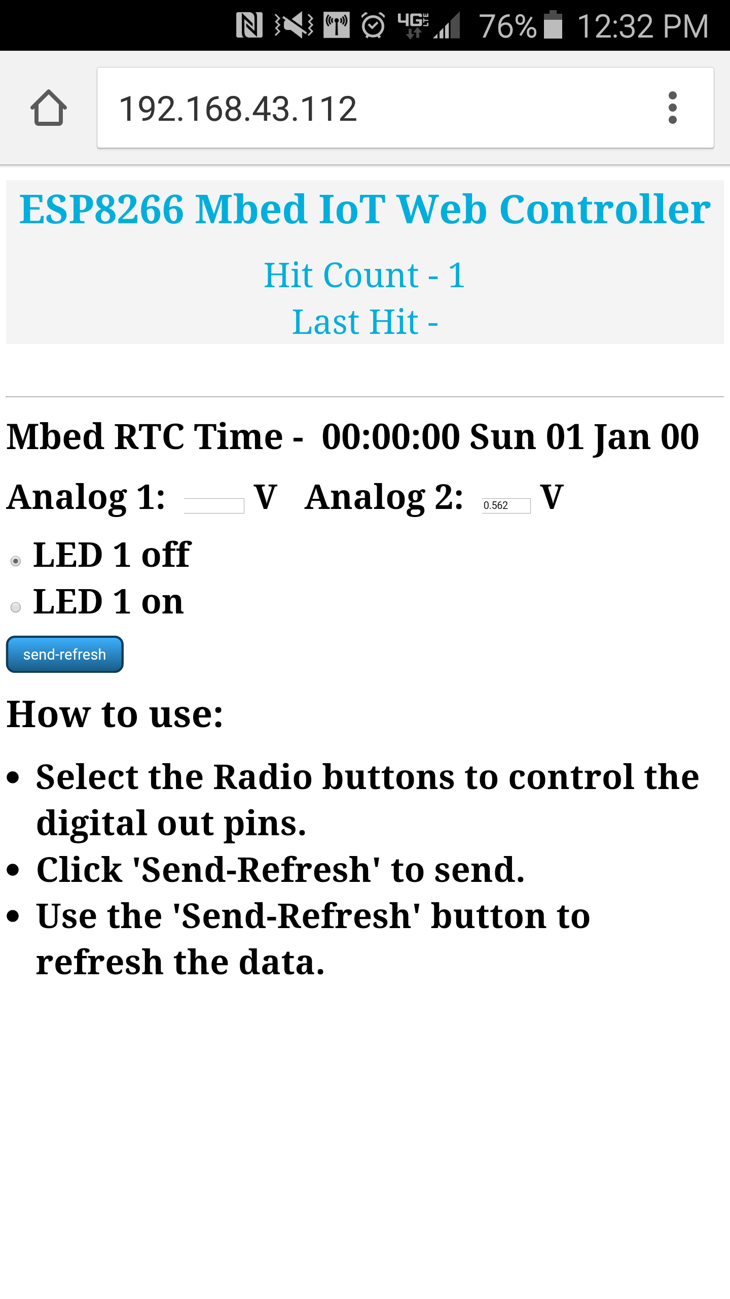
Using the mbed, an Sharp IR distance Sensor, speakers, and the ESP8266 wifi module, we built a robot that accomplishes several goals. First, the robot will adjust the speed based on the distance of an obstacle from IR sensor. The closer the obstacle, usually the user's hand, the faster the robot will move. The speaker outputs a frequency correlating with the speed of the robot. So, the faster the robot, the higher the frequency of sound emitted. We connected our robot to the internet and displayed a web page that allows the user to monitor the analog voltage from the IR sensor. It also allows the user to change the brightness level of the built-in mbed LEDs.
Hookup Guide
We need to hookup the speaker, H-bridge, IR Sensor, and WiFi Module
Speaker
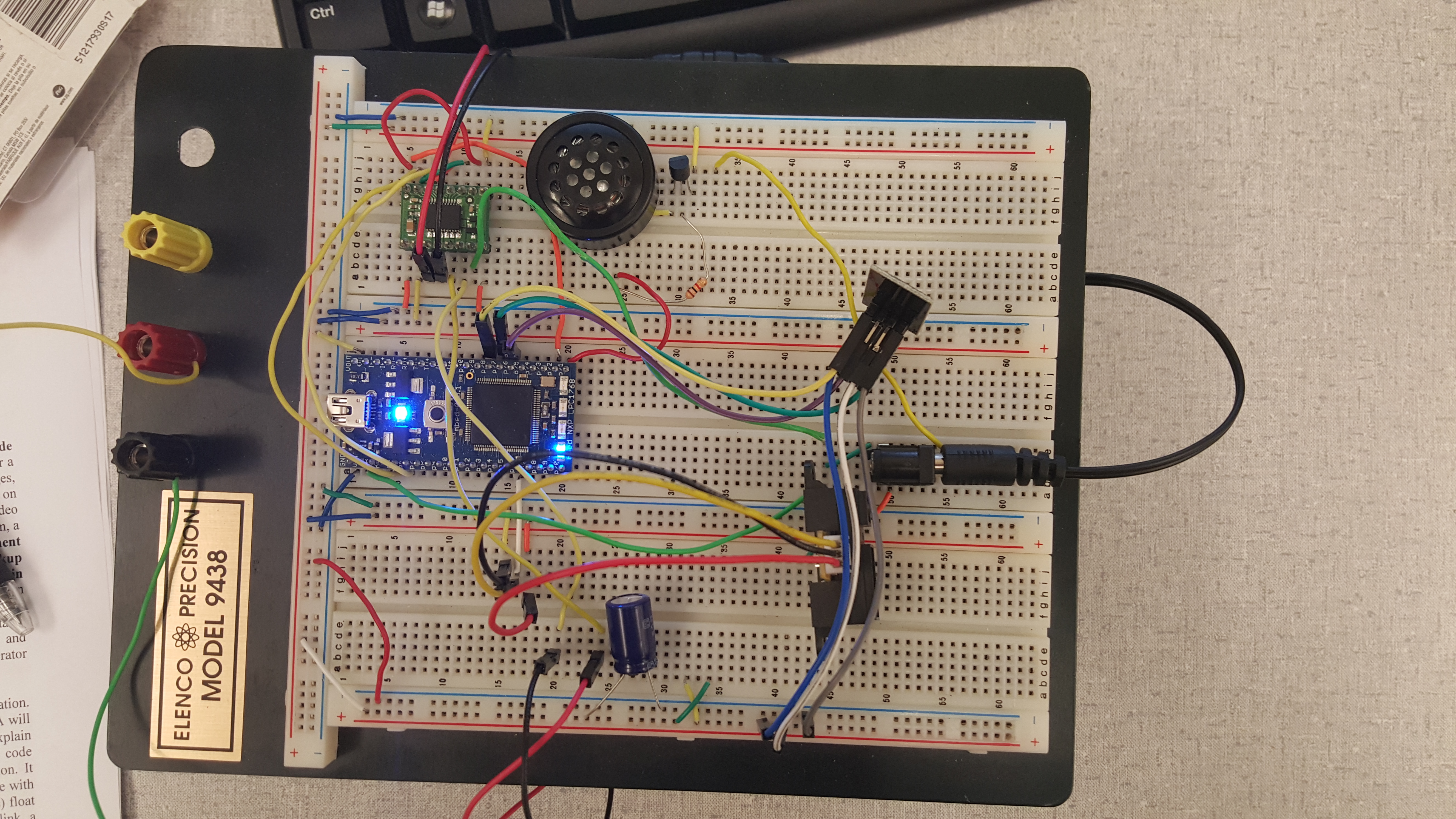
To connect the speaker, we will need a 2N3904 transistor and a Sparkfun PCB speaker. the emitter terminal of the transistor will need to be hooked up to ground, while the base of the transistor will go to your PWM output pin of the MBED (we used p21). Note: this connection from the base to the PWM pin will require a 220 to 1000 ohm resistor. The collector of the transistor goes to the negative terminal of the speaker, and the positive terminal of the speaker connects to the MBEDs Vout (3.3V) or VU (5V) pin.
| MBED Pin | 2N3904 Transistor | Speaker |
|---|---|---|
| P21 | Base | |
| GND | Emitter | |
| Vout | + Terminal | |
| Collector | - Terminal |
HBridge
For the H-bridge, the three ground terminals will need to be connected to ground, and VCC will connect the the MBEDs Vout (3.3V). The VMOT will require an external power supply of 5V. PWMA and PWMB are both connect to p22. A and B in1 are connected to p6, and A and B in2 are connected to p5. The inverse of the standby pin is connected Vout.The negative lead of motor a is connected to AO1, and the positive lead of motor a is connected to AO2. The negative lead of motor B is connected to BO2, and the positive lead of motor B is connected to BO1.
| MBED Pins | H-Bridge | External 5V Power Supply | Motors |
|---|---|---|---|
| GND | GND | GND | |
| Vout | VCC, STDBY | ||
| VMOT | + 5V Power Supply | ||
| P22 | PWMA, PWMB | ||
| P5 | Ain2, Bin2 | ||
| P6 | Ain1, Bin1 | ||
| AO1, BO1 | - | ||
| AO2, BO2 | + |
IR Sensor
The red wire is connected to Vout of the MBED, and the black wire is connected to GND of the MBED. The yellow wire is the analog input wire that is connected to p16.
| MBED Pins | Sharp Distance Sensor |
|---|---|
| P16 | Yellow Wire |
| GND | Black Wire |
| Vout | Red Wire |
WiFi
For the ESP8266 WiFi module, you will need M/F jumper cables. The power lines will need to be coupled with a 330 uF capacitor, with the positive lead going to the Vout rail, and the negative lead going to the GND rail. VCC on the ESP8266 connects to the Vout pin on the MBED. Reset goes to p26, and the RX on the ESP8266 goes to TX on the MBED (p28), while TX on the ESP8266 goes to RX on the MBED (p27). CH_PD goes to Vout on the MBED.
| MBED Pins | ESP8266 WiFi Module | 330 uF capacitor |
|---|---|---|
| GND | GND | - lead of capacitor |
| Vout | VCC and CH_PD | + lead of capacitor |
| P26 | Reset | |
| P28 (TX) | RX | |
| P27 (RX) | TX |
Images


Video
Code/Libraries
Import programIoTIRDistanceSensingRobot
IoT IR Distance Sensor Robot
Please log in to post comments.
