ECE4180 Final Project
Self-Parking Car
Team
- Sungwoo Han
- Sangwon Song
Objective
To design a remote driving controller an automatic parking system on a mini-car using mbed microcontrollers, DC motors, ultrasonic sensors, H-Bridge, and bluetooth module. For the automatic parking system, the system will be demonstrated in designed map.
Parts List
- mbed LPC1768(2): mbed microcontroller to operate the entire functions of this project
- Adafruit Bluefruit LE UART Friend Bluetooth Module: The bluetooth module for this project to perform the connection between the mini-car and a smart phone.
- HC-SR04(7): The ultrasonic sensor to detect the distance between the mini-car and the wall of the map.
- uLCD144G2: LCD display to show the status of the car moving status
- TB6612FNG Dual Motor Driver Carrier: H-Bridge driver module for DC motors
- ROB-12629: Hall Effect Sensor for measuring rpm and distance the car travels.
- Mini-car kit: The mini-car kit to build a small size car with two wheels. Specific hardware in this project:
- DC Barrel Jack: An additional power source. 4 of AA battery are needed.
- DC Motor(2): To perform movements of this project
- Shadow Chassis: Chassis of the mini car
- Other supplies
- Breadboards: For wiring
- Wires: Electrical connections among parts and boards
- External portable battery: An additional power source for the master mbed
Program Description
In this project, two major modes are controlled by Bluetooth: 1. Manual driving mode. 2. Autonomous parking mode.
During the first mode, a user can manually control driving motion of the mini-car by using the bluetooth connection between the car and the mobile device, Adafruit Bluefruit LE friend, connected to the mbed (Master). In the Bluetooth mobile application, there are number pads (1 to 4) and 4 directions of arrow keys (forward, right, left, and backward).
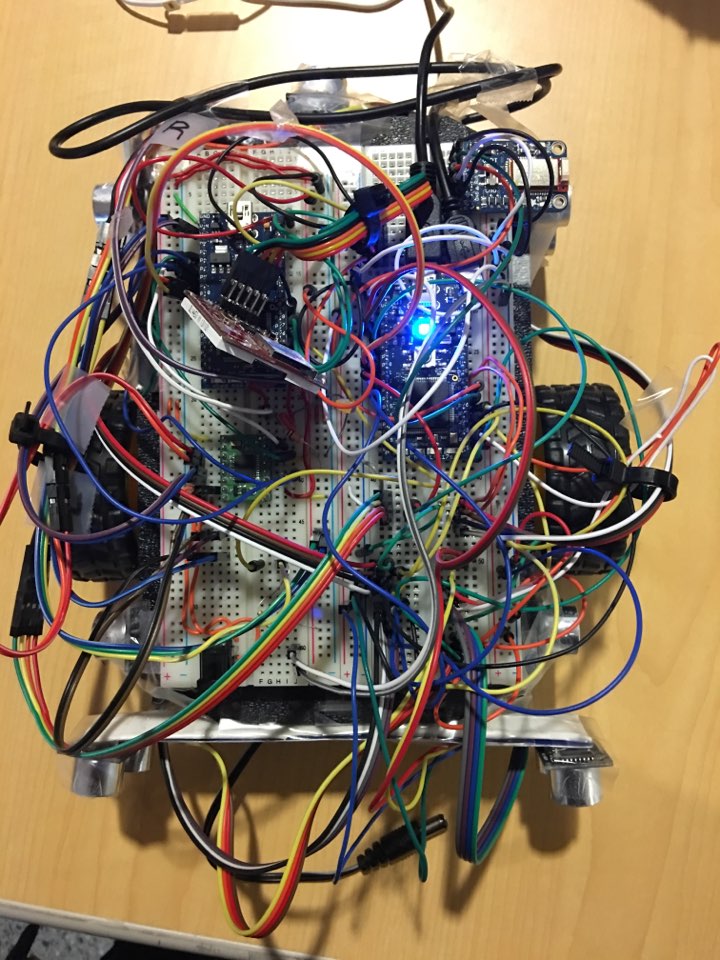
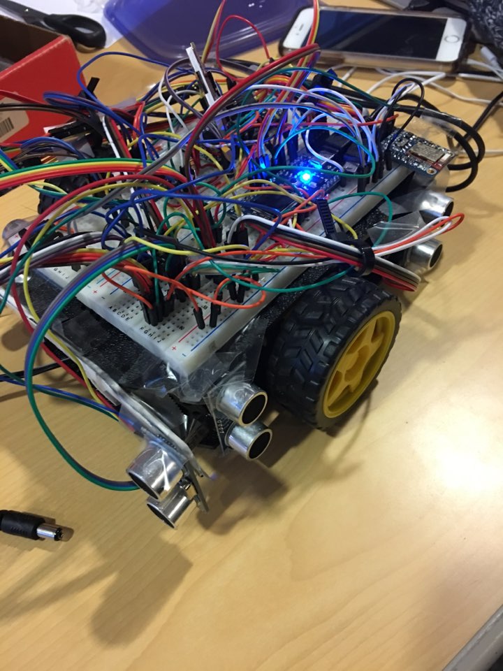
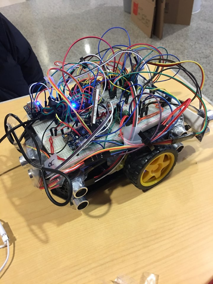
During the second mode, autonomous parking system, the mini-car can detect an appropriate parking space and park itself automatically. To get into the autonomous parking stage, the user presses the number pad (1) on the mobile application, and the mini-car starts moving and detects distances between the sides of the car and the walls in order to drive around the parking lot (our map), until it finds an empty spot. When it finally finds the parking spot, it will park itself in. Around the mini-car, there are seven ultrasonic sensors; 1 front sensor, 2 right sensors (front, rear), 2 left sensors (front, rear), and 2 back sensors (left, right). These sensors measures the distances and continuously send the signals to the mbed (master). When the master mbed receives the signals, it calculated the situation and determine a proper action such as 'move forward', 'tilt to the left', 'turn right', and so on. Once the car finds appropriate parking space, it slowly parks into there and shows "park done" message on the uLCD screen.
Block Diagram

Wiring


PinOuts
2 mbed microcontrollers, 7 ultrasonic sensors, 2 DC motors with H-Bridge module and hall effect sensors, and 1 bluetooth module are used.
- First mbed (master)
| Mbed | Ultrasonic sensor | Bluetooth module | Mbed (Slave) |
|---|---|---|---|
| GND | GND(for each sensor, 7 connections total) | GND, CTS | |
| VU(5V) | Vcc(for each sensor, 7 connections total) | Vin | |
| P8 | Trig(Front Sensor) | ||
| P11 | Echo(Front Sensor) | ||
| P25 | Trig(Left Sensor, Front) | ||
| P26 | Echo(Left Sensor, Front) | ||
| P12 | Trig(Left Sensor, Rear) | ||
| P13 | Echo(Left Sensor, Rear) | ||
| P21 | Trig(Back Sensor, Right) | ||
| P22 | Echo(Back Sensor, Right) | ||
| P5 | Trig(Back Sensor, Left) | ||
| P6 | Echo(Back Sensor, Right) | ||
| P23 | Trig(Right Sensor, Right) | ||
| P24 | Echo(Right Sensor, Right) | ||
| P29 | Trig(Right Sensor, Front) | ||
| P30 | Echo(Right Sensor, Front) | ||
| P27(Serial RX) | TXO | ||
| P28(Serial TX) | RXI | ||
| P9(Serial TX) | P10(Serial RX) | ||
| P10(Serial RX) | P9(Serial TX) |
- Second mbed(slave)
| Mbed | Device | Info | Side |
|---|---|---|---|
| GND | |||
| Vin | External Battery | ||
| Vout | VCC | ||
| p5 | DCMotor | Fwd | Right |
| p6 | DCMotor | Rev | Right |
| p7 | DCMotor | Fwd | Left |
| p8 | DCMotor | Rev | Left |
| p9(Serial TX) | p10(Serial RX) | UART | |
| p10(Serial RX) | p9(Serial TX) | UART | |
| p21 | DCMotor | PWM | Right |
| p22 | DCMotor | PWM | Left |
| p24 | HallEffect Sensor | Left | |
| p25 | HallEffect Sensor | Right | |
| p27 | uLCD | TX | |
| p28 | uLCD | RX | |
| p29 | uLCD | Rev |
Demo
Program
- Master mbed code
Import program4180_Final_MasterWithBT_Fin
ece 4180 final project master mbed code
- Slave mbed code
Import program4180_Final_halleffectSensor_Fin
4180 final project slave mbed code
Please log in to post comments.
