Important changes to repositories hosted on mbed.com
Mbed hosted mercurial repositories are deprecated and are due to be permanently deleted in July 2026.
To keep a copy of this software download the repository Zip archive or clone locally using Mercurial.
It is also possible to export all your personal repositories from the account settings page.
Dependencies: mbed ESP8266_WebServer
You are viewing an older revision! See the latest version
Updating ESP8266 Firmware
How to update the ESP8266 Module's firmware
BEFORE YOU BEGIN Note that this information has been cobbled together from multiple websites and the official Espressif AT Github Repository. It worked for me, and may work for you, but I take no responsibility if your ESP8266 module stops working after attempting this.
Required hardware and software
- You will need a Windows PC for this update
- You will need some form of USB to Serial converter that allows operation at 3.3V. I used a Foca board. It allows easy plugging into a breadboard, which then allows me to hookup the pins of the ESP8266 module via jumper wires to the corresponding pins on the USB<->Serial board.
- The firmware updating software only works on COM ports 1-6. If your USB<->Serial device enumerates to a higher port number than that, you will have to change it via Device Manager in Windows.
- You can download all the required files in this ZIP file esp_flasher.zip
Connecting it up
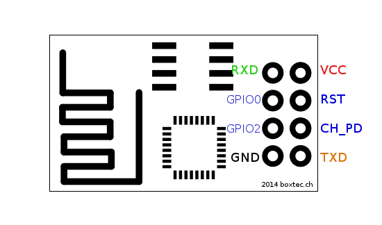
Above is a pin out diagram for the ESP8266 Module
You need to hookup these pins from the ESP8266 to your USB<->Serial board:
- VCC to 3.3V
- GND to ground
- CH_PD to 3.3V
- TXD to RX, RXD to TX (this may depend on the USB<->Serial board you are using. If it doesn't work, try swapping them around)
- GPIO0 to ground (for the duration of firmware upgrading. After all the upgrades have been loaded, it needs to be disconnected)
You will need to unplug and re-plug the USB cable 4 times during the process, so make sure you can reach it easily
Flashing the firmware
Inside the esp_flasher.zip file, you will find a couple of .bin files, an executable named XTCOM_UTIL.exe and also a readme.txt file containing the addresses to flash each of the .bin files to, which I will duplicate here for reference
boot_v1.1.bin---------------->0x00000
user1.bin-------------------->0x01000
esp_init_data_default.bin---->0x7C000
blank.bin-------------------->0x7E000
Steps to flash each .bin file
- Power everything by plugging into USB port
- Start XTCOM_UTIL.exe
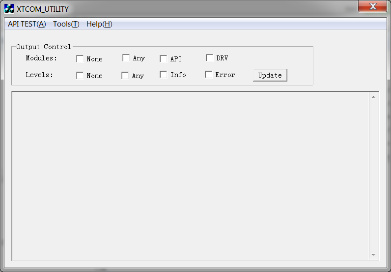
- Hit Tools -> Config Device in the menu
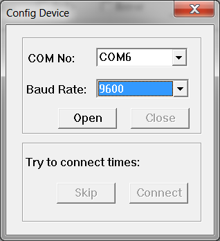
- Configure the settings to whatever COM port you are using, and 9600 baud rate
- Click on "Open". You should receive a notification saying "Operation Succeeded!"
- Click on "Connect". The "Try to connect times: " message should increment a few times as the utility tries to contact the module.
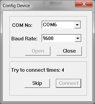
You should receive a notification about success before hitting 20 times.<<info>>If you don't, then make sure your connections are correct, and perhaps try swapping the RX and TX pins around.<</info>> - Close the "Config Device" window.
- Hit API TEST -> (4) Flash Image Download in the menu
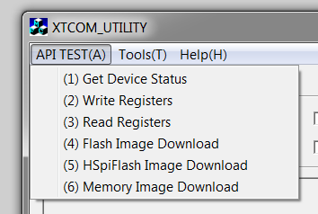
- Select the .bin file to flash, and configure the correct destination address as in the readme.txt file (For Example: boot_v1.1.bin @ 0x00000)
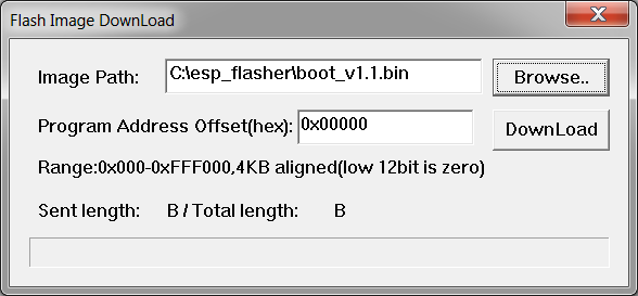
- Click on "Download" and wait for the flashing to complete.
- Close down the entire XTCOM_UTIL program, and unplug the USB. * VERY IMPORTANT This must be done between each .bin file
- Repeat each of the above steps fort each of the .bin files, making sure to leave the GPIO0 pin grounded during the entire process.
Important FInal Info
Finally, you can remove the ground from GPIO0, and reapply power to the module. It should start up with the new firmware. However be aware that the new baud rate will now be 115200 and not 9600 anymore.
I have also had to move/remove some of the connections between the ESP8266 module and the Nucleo once putting the module back. Specifically, I removed the RST pin from the Nucleo, and now ground it manually on the odd occasion I need to hard-reset the module. I also moved the CH_PD pin over to hard-wired to 3.3V. Not sure why it was giving me problems on the GPIO pin of the Nucleo, but it was, and it's not really required.