Gesture based robotic arm control
Description
Robotic arms are becoming increasingly popular in several fields such as industrial automation, medical applications such as remote key-hole surgeries and military applications because of its preciseness and accuracy. In certain critical applications such as performing surgeries or diffusing a bomb, robotic arms could be of tremendous use to save lives. In such applications, controlling the robotic arm precisely is of utmost importance. Currently, such robotic arms are typically controlled using a joystick that is wired to the robotic arm.
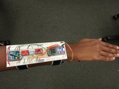
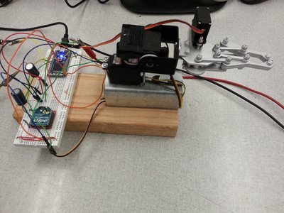
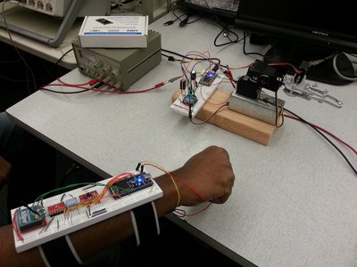
We have designed a robotic arm with 2 degrees of freedom that is wirelessly synchronized to a human arm and can emulate the movements of a human arm. We have used an inertial measurement unit connected to an mbed, to measure the exact position of a human arm. This information (in the form of Euler angles row, pitch and yaw) is then transmitted to the mbed controlling the robotic arm using an xbee wireless module. The mbed on the robotic arm computes the pulsewidth of the PWM signals for the servos that are required to move the arm to the position indicated by the Euler angles. We used the Pitch and Yaw angles to control 2 servos mounted perpendicularly.
To demonstrate pick-and-place functionality, we fixed a gripper at the end of the frame. The control signal for the gripper is generated using a switch which is placed along with the IMU on the human arm and is transmitted along with the Euler angles.
Components used
- 2 mbeds (LPC1768)
- ADXL345 accelerometer
- ITG3200 3-axis gyroscope
- Maxstream Xbee transmitter and Receiver
- Sparkfun robotic arm gripper
- 2 servos
Block Diagram

Connections
Transmitter Module
| mbed | ADXL 345 |
|---|---|
| p5 | SDA |
| p6 | SDO |
| p7 | SCL |
| p8 | CS |
| 3.3v | VCC |
| GND | GND |
| mbed | ITG 3200 |
| p9 | SDA (via pullup resistor) |
| p10 | SCL (via pullup resistor) |
| GND | GND |
| 3.3v | VDD |
| 3.3v | VIO |
| mbed | xbee transmitter |
| p28 | p3 |
| p21 | p5 |
| 3.3v | p1 |
| GND | p10 |
Receiver Module
| mbed | xbee receiver |
|---|---|
| p10 | p2 |
| p8 | p5 |
| 3.3v | p1 |
| GND | p10 |
| mbed | Servos |
| p21 | Yaw axis motor PWM |
| p22 | Pitch axis motor PWM |
| p23 | Gripper motor PWM |
Transmitter module code
/**
 TRANSMITTER MODULE - GET THE EULER ANGLES FROM IMU UNIT AND TRANSMIT VIA ZIGBEE
 */
#include "IMUfilter.h"
#include "ADXL345.h"
#include "ITG3200.h"

//Gravity at Earth's surface in m/s/s
#define g0 9.812865328
//Number of samples to average.
#define SAMPLES 4
//Number of samples to be averaged for a null bias calculation
//during calibration.
#define CALIBRATION_SAMPLES 128
//Convert from radians to degrees.
#define toDegrees(x) (x * 57.2957795)
//Convert from degrees to radians.
#define toRadians(x) (x * 0.01745329252)
//ITG-3200 sensitivity is 14.375 LSB/(degrees/sec).
#define GYROSCOPE_GAIN (1 / 14.375)
//Full scale resolution on the ADXL345 is 4mg/LSB.
#define ACCELEROMETER_GAIN (0.004 * g0)
//Sampling gyroscope at 200Hz.
#define GYRO_RATE   0.005
//Sampling accelerometer at 200Hz.
#define ACC_RATE    0.005
//Updating filter at 40Hz.
#define FILTER_RATE 0.1

Serial xbee1(p28, p27);
DigitalOut rst1(p21);
DigitalIn grab(p23);
Serial pc(USBTX, USBRX);

//At rest the gyroscope is centred around 0 and goes between about
//-5 and 5 counts. As 1 degrees/sec is ~15 LSB, error is roughly
//5/15 = 0.3 degrees/sec.
IMUfilter imuFilter(FILTER_RATE, 0.3);
ADXL345 accelerometer(p5, p6, p7, p8);
ITG3200 gyroscope(p9, p10);
Ticker accelerometerTicker;
Ticker gyroscopeTicker;
Ticker filterTicker;

//Offsets for the gyroscope.
//The readings we take when the gyroscope is stationary won't be 0, so we'll
//average a set of readings we do get when the gyroscope is stationary and
//take those away from subsequent readings to ensure the gyroscope is offset
//or "biased" to 0.
double w_xBias;
double w_yBias;
double w_zBias;

//Offsets for the accelerometer.
//Same as with the gyroscope.
double a_xBias;
double a_yBias;
double a_zBias;

//Accumulators used for oversampling and then averaging.
volatile double a_xAccumulator = 0;
volatile double a_yAccumulator = 0;
volatile double a_zAccumulator = 0;
volatile double w_xAccumulator = 0;
volatile double w_yAccumulator = 0;
volatile double w_zAccumulator = 0;

//Accelerometer and gyroscope readings for x, y, z axes.
volatile double a_x;
volatile double a_y;
volatile double a_z;
volatile double w_x;
volatile double w_y;
volatile double w_z;

//Buffer for accelerometer readings.
int readings[3];
//Number of accelerometer samples we're on.
int accelerometerSamples = 0;
//Number of gyroscope samples we're on.
int gyroscopeSamples = 0;


//Set up the ADXL345 appropriately.
void initializeAcceleromter(void);
//Calculate the null bias.
void calibrateAccelerometer(void);
//Take a set of samples and average them.
void sampleAccelerometer(void);
//Set up the ITG3200 appropriately.
void initializeGyroscope(void);
//Calculate the null bias.
void calibrateGyroscope(void);
//Take a set of samples and average them.
void sampleGyroscope(void);
//Update the filter and calculate the Euler angles.
void filter(void);

void initializeAccelerometer(void) {

    //Go into standby mode to configure the device.
    accelerometer.setPowerControl(0x00);
    //Full resolution, +/-16g, 4mg/LSB.
    accelerometer.setDataFormatControl(0x0B);
    //200Hz data rate.
    accelerometer.setDataRate(ADXL345_200HZ);
    //Measurement mode.
    accelerometer.setPowerControl(0x08);
    //See http://www.analog.com/static/imported-files/application_notes/AN-1077.pdf
    wait_ms(22);

}

void sampleAccelerometer(void) {

    //Have we taken enough samples?
    if (accelerometerSamples == SAMPLES) {

        //Average the samples, remove the bias, and calculate the acceleration
        //in m/s/s.
        a_x = ((a_xAccumulator / SAMPLES) - a_xBias) * ACCELEROMETER_GAIN;
        a_y = ((a_yAccumulator / SAMPLES) - a_yBias) * ACCELEROMETER_GAIN;
        a_z = ((a_zAccumulator / SAMPLES) - a_zBias) * ACCELEROMETER_GAIN;

        a_xAccumulator = 0;
        a_yAccumulator = 0;
        a_zAccumulator = 0;
        accelerometerSamples = 0;

    } else {
        //Take another sample.
        accelerometer.getOutput(readings);

        a_xAccumulator += (int16_t) readings[0];
        a_yAccumulator += (int16_t) readings[1];
        a_zAccumulator += (int16_t) readings[2];

        accelerometerSamples++;

    }

}

void calibrateAccelerometer(void) {

    a_xAccumulator = 0;
    a_yAccumulator = 0;
    a_zAccumulator = 0;

    //Take a number of readings and average them
    //to calculate the zero g offset.
    for (int i = 0; i < CALIBRATION_SAMPLES; i++) {

        accelerometer.getOutput(readings);

        a_xAccumulator += (int16_t) readings[0];
        a_yAccumulator += (int16_t) readings[1];
        a_zAccumulator += (int16_t) readings[2];

        wait(ACC_RATE);

    }

    a_xAccumulator /= CALIBRATION_SAMPLES;
    a_yAccumulator /= CALIBRATION_SAMPLES;
    a_zAccumulator /= CALIBRATION_SAMPLES;

    //At 4mg/LSB, 250 LSBs is 1g.
    a_xBias = a_xAccumulator;
    a_yBias = a_yAccumulator;
    a_zBias = (a_zAccumulator - 250);

    a_xAccumulator = 0;
    a_yAccumulator = 0;
    a_zAccumulator = 0;

}

void initializeGyroscope(void) {

    //Low pass filter bandwidth of 42Hz.
    gyroscope.setLpBandwidth(LPFBW_42HZ);
    //Internal sample rate of 200Hz. (1kHz / 5).
    gyroscope.setSampleRateDivider(4);

}

void calibrateGyroscope(void) {

    w_xAccumulator = 0;
    w_yAccumulator = 0;
    w_zAccumulator = 0;

    //Take a number of readings and average them
    //to calculate the gyroscope bias offset.
    for (int i = 0; i < CALIBRATION_SAMPLES; i++) {

        w_xAccumulator += gyroscope.getGyroX();
        w_yAccumulator += gyroscope.getGyroY();
        w_zAccumulator += gyroscope.getGyroZ();
        wait(GYRO_RATE);

    }

    //Average the samples.
    w_xAccumulator /= CALIBRATION_SAMPLES;
    w_yAccumulator /= CALIBRATION_SAMPLES;
    w_zAccumulator /= CALIBRATION_SAMPLES;

    w_xBias = w_xAccumulator;
    w_yBias = w_yAccumulator;
    w_zBias = w_zAccumulator;

    w_xAccumulator = 0;
    w_yAccumulator = 0;
    w_zAccumulator = 0;

}

void sampleGyroscope(void) {

    //Have we taken enough samples?
    if (gyroscopeSamples == SAMPLES) {

        //Average the samples, remove the bias, and calculate the angular
        //velocity in rad/s.
        w_x = toRadians(((w_xAccumulator / SAMPLES) - w_xBias) * GYROSCOPE_GAIN);
        w_y = toRadians(((w_yAccumulator / SAMPLES) - w_yBias) * GYROSCOPE_GAIN);
        w_z = toRadians(((w_zAccumulator / SAMPLES) - w_zBias) * GYROSCOPE_GAIN);

        w_xAccumulator = 0;
        w_yAccumulator = 0;
        w_zAccumulator = 0;
        gyroscopeSamples = 0;

    } else {
        //Take another sample.
        w_xAccumulator += gyroscope.getGyroX();
        w_yAccumulator += gyroscope.getGyroY();
        w_zAccumulator += gyroscope.getGyroZ();

        gyroscopeSamples++;

    }

}

void filter(void) {

    //Update the filter variables.
    imuFilter.updateFilter(w_y, w_x, w_z, a_y, a_x, a_z);
    //Calculate the new Euler angles.
    imuFilter.computeEuler();

}

int main() {
    char send[3];
    int tosend[3];
    // reset the xbees (at least 200ns)
    rst1 = 0;
    //rst2 = 0;
    wait_ms(1);
    rst1 = 1;
    //rst2 = 1;
    wait_ms(1);

    //Initialize inertial sensors.
    initializeAccelerometer();
    calibrateAccelerometer();
    initializeGyroscope();
    calibrateGyroscope();

    //Set up timers.
    //Accelerometer data rate is 200Hz, so we'll sample at this speed.
    accelerometerTicker.attach(&sampleAccelerometer, 0.005);
    //Gyroscope data rate is 200Hz, so we'll sample at this speed.
    gyroscopeTicker.attach(&sampleGyroscope, 0.005);
    //Update the filter variables at the correct rate.
    filterTicker.attach(&filter, FILTER_RATE);

    while (1) {

        wait(FILTER_RATE);


        pc.printf("%f,%f,%f\n",toDegrees(imuFilter.getRoll()),toDegrees(imuFilter.getPitch()),toDegrees(imuFilter.getYaw()));
        if(grab)tosend[2]=99;
        if(!grab)tosend[2]=77;
        tosend[0]=(int)toDegrees(imuFilter.getYaw());
        if(tosend[0]<0)tosend[0]=0;
        tosend[1]=(int)toDegrees(imuFilter.getPitch());
        if(tosend[1]<0)tosend[1]=tosend[1]+180;

        ////// convert integers to characters before transmitting   ////////

        send[0]=tosend[0]&0xFF;
        send[1]=tosend[1]&0xFF;
        send[2]=tosend[2]&0xFF;

        ////// transmit using zigbee ///////////

        xbee1.putc(send[0]);
        xbee1.putc(send[1]);
        xbee1.putc(send[2]);

    }

}
Receiver module code
#include "mbed.h"

Serial xbee1(p9, p10);
DigitalOut rst1(p8);
PwmOut yaw(p21);
PwmOut pitch(p22);
PwmOut grab(p23);
Serial pc(USBTX, USBRX);

int main() {
    char recieve;
    yaw.period(0.020);
    pitch.period(0.020);
    grab.period(0.020);
    int got[3];
    float pwidth[2];
    // reset the xbees (at least 200ns)
    rst1 = 0;
    //rst2 = 0;
    wait_ms(1);
    rst1 = 1;
    //rst2 = 1;
    wait_ms(1);

    while(1) {
        if(xbee1.readable()) {
            ///////// YAW ANGLE ///////////
            recieve=xbee1.getc();
            got[0]=((0<<8)|recieve);
            got[0]=2*got[0];
            if(got[0]>180)got[0]=180;
            if(got[0]<0)got[0]=0;
            pwidth[0]=(float)got[0]/(180*1000);
            yaw.pulsewidth(0.001+(pwidth[0]));
            printf("got[0]: %d",got[0]);
            printf("yaw pulsewidth: %f\n\r",0.001+pwidth[0]);

            ///////// PITCH ANGLE /////////
            recieve=xbee1.getc();
            got[1]=((0<<8)|recieve);
            if(got[1]>90)got[1]=got[1]-180;
            got[1]=got[1]*2;
            if(got[1]>90)got[1]=90;
            if(got[1]<-90)got[1]=-90;
            pwidth[1]=(float)got[1]/(180*1000);
            pitch.pulsewidth(0.0015+(pwidth[1]));
            printf("got[1]: %d",got[1]);
            printf("pitch pulsewidth: %f\n\r",0.0015+pwidth[1]);

            ////////// GRAB CONTROL ////////
            recieve=xbee1.getc();
            got[2]=((0<<8)|recieve);
            if(got[2]==77)
                    grab.pulsewidth(0.001);
           if(got[2]==99)
                    grab.pulsewidth(0.0017);
            printf("Grab: %d\n\r\n",got[2]);

        }

    }
}
Images
Transmitter module strapped to forearm

Receiver module

Complete Setup

Demonstration Video
Information
- Do not forget to tie the mbed's ground and the servo power supply grounds together.
- Please ensure that the power supply can deliver enough current to 3 servo motors simultaneously.
- To reduce spikes in the power line due to the high current, you could connect a capacitor (1000uF or higher)
References
1 comment on Gesture based robotic arm control:
Please log in to post comments.

how to control the gripper without using the switch? - instead by fingers THANKS