Mbed Rhythm
Collaborators: Saketh Poda and Ashwin Subramanian
Summary
For our project, we decided to create a game that tests a person's reaction time. The game uses an mbed LPC1768, a uLCD (uLCD-144-G2), a digital joystick, an SD card reader, and a speaker in conjunction with a transistor.
When the game starts, a title screen is displayed and the user can decide which level to play based on which direction the joystick is pushed. Each level has ten rounds, and in each round, a picture of an arrow or a circle will be displayed on the screen, and the user must push the joystick in the direction the arrow points toward. If the picture is a circle, the joystick must be pressed in the z-axis rather than pushed up, down, left, or right. Each level provides the user a different amount of time to push the joystick (level 1: 3 second interval between pictures, level 2: 2 second interval, level 3: 1 second interval). Every time the user pushes the joystick in the correct direction, a point is added to the score. The maximum possible score for a game is 10 and the minimum is 0. If the user does does not push the joystick within the level's time interval or if the user pushes the joystick in the wrong direction, the round is over but no points are given.
After a game ends, a results screen is displayed with the total score (0 to 10) for that game and the average reaction time, which is the average of the ten reaction times (one per round) for that game. The user will be asked if he or she wants to play again. If the user chooses "yes," he or she will be taken back to the title screen and all game statistics will be reset. If the user chooses "no," a thank you screen will pop up.
The game uses three sound effects, with one when the game starts, one when the results screen is displayed, and one at the thank you screen. The SD card reader stores the wav files to be played by the speaker.
Components
- mbed LPC1768: https://developer.mbed.org/platforms/mbed-LPC1768/
- uLCD-144-G2: https://developer.mbed.org/users/4180_1/notebook/ulcd-144-g2-128-by-128-color-lcd/
- Digital Joystick: https://developer.mbed.org/users/4180_1/notebook/using-a-navigation-switch-digital-joystick/
- Speaker: https://developer.mbed.org/users/4180_1/notebook/using-a-speaker-for-audio-output/
- SD Card Reader: https://developer.mbed.org/cookbook/SD-Card-File-System
Wiring Guides
uLCD-144-G2
- mbed ... uLCD Header ... uLCD Cable
- VU = 5V ... 5V ... 5V
- Gnd ... Gnd ... Gnd
- TX = P9 ... RX ... TX
- RX = P10 ... TX ... RX
- P11 ... Reset ... Reset
Digital Joystick
- mbed ... Joystick
- Gnd ... -
- P9 ... U
- P8 ... C
- P7 ... L
- P6 ... D
- P5 ... R
- nc ... +
SD Card Reader
- mbed ...SD Card Reader
- P8 ... CS
- P5 ... DI
- Vout ... VCC
- P7 ... SCK
- Gnd ...Gnd
- P6 ... DO
Speaker

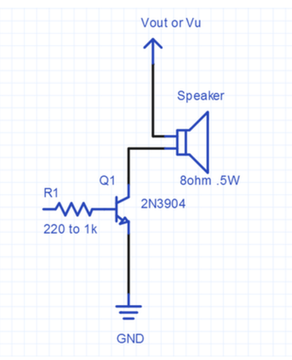
Note: One side of resistor R1 is connected to the base of the transistor, and the other side of R1 is connected to AnalogOut on the mbed (pin 18).
Circuit

Video Demonstration
Program
Import programRhythmGame
Rhythm game with mbed
Please log in to post comments.
