OLED
 Simon Blandford.
2
replies
Simon Blandford.
2
replies
Driver for the Densitron DD-160128FC-1A
This is a 160x128 OLED display accessed via the SPI interface using the supplied driver. The driver supports the display of colour, fills, text and individual pixels. The display orientation can be selected by the driver too. The driver is based on MobileLCD written by Simon Ford and will work as a plug-in replacement except for the different width and height of the display. The display uses a Syncoam SEPS525F driver chip.
Hardware
The display itself, DD-160128FC-1A, is available (at time of writing) from Farnell as part number 1498857. This consists of the glass and a driver chip on a flexfoil connector. For prototyping I recommend using the Densitron connection board, EVK-CONNECT-010, available from Farnell as part number 1500758. This fans out the pins to a more manageable 0.1'' pitch strip.
The display requires two power supplies, 3v3 for the logic and 13V for the display.
Connections
| Pin no. | EVK Pin name | Signal name | MBed Pin |
| 1 | GND | GND | GND |
| 2 | GND | GND | |
| 3 | GND | GND | |
| 4 | GND> | GND | |
| 5 | VCC_IN | +13V supply | |
| 6 | GND | GND | |
| 7 | VDD_IN | +3V3 supply | |
| 8 | GND | GND | |
| 9 | not connected | not connected | |
| 10 | VSYNCO | not connected | |
| 11 | DOTCLK | GND | |
| 12 | VSYNC | GND | |
| 13 | ENABLE | GND | |
| 14 | HSYNC | GND | |
| 15 | not connected | not connected | |
| 16 | D9 | GND | |
| 17 | not connected | not connected | |
| 18 | not connected | not connected | |
| 19 | not connected | not connected | |
| 20 | not connected | not connected | |
| 21 | not connected | not connected | |
| 22 | not connected | not connected | |
| 23 | not connected | not connected | |
| 24 | not connected | not connected | |
| 25 | not connected | not connected | |
| 26 | not connected | not connected | |
| 27 | DC/DC EN | not connected | |
| 28 | CSB | CS | P8 |
| 29 | RESETB | RST | P9 |
| 30 | RS | RS | P10 |
| 31 | WRB | GND | |
| 32 | RDB | GND | |
| 33 | D17 | CLK | P7 |
| 34 | D16 | MOSI | P5 |
| 35 | D15 | GND | |
| 36 | D14 | GND | |
| 37 | D13 | GND | |
| 38 | D12 | GND | |
| 39 | D11 | GND | |
| 40 | D10 | GND |
Link positions
| PS | VSS |
| CPU | VSS |
| VDDIO | VDD |
Driver and test program
#include
#include "mbed.h"
#include "OLEDSeps525f.h"
OLEDSeps525f lcd(p5, p6, p7, p8, p9, p10);

int main() {
    //Test background and clear screen
    lcd.background(0x0000FF);
    lcd.cls();

    //Test colour and fill
    lcd.fill(0, 50, lcd.width(), 10, 0x00FF00);
    lcd.fill(50, 0, 10, lcd.height(), 0xFF0000);
    //Test pixel writing
    for(int i=0; i!=lcd.width(); i++) {
        lcd.pixel(i, 80 + sin((float)i / 5.0)*10, 0x000000);
    }
    lcd.locate(0,1);

    //Test text and newline
    lcd.printf("OLED\ndriver\n");
    //Test tab
    lcd.printf("\ttab\t2\t3\t4");
    lcd.locate(0,10);

    //Test control codes
    lcd.printf("\t*\v*\v\b\b*\r*");

    //Test orientation
    lcd.locate(lcd.columns()/2-(strlen("Top  ")/2),1);
    lcd.printf("Top %u",lcd.orientation());
    lcd.orientation(1);
    lcd.locate(lcd.columns()/2-(strlen("Right  ")/2),1);
    lcd.printf("Right %u",lcd.orientation());
    lcd.orientation(2);
    lcd.locate(lcd.columns()/2-(strlen("Bottom  ")/2),1);
    lcd.printf("Bottom %u",lcd.orientation());
    lcd.orientation(3);
    lcd.locate(lcd.columns()/2-(strlen("Left  ")/2),1);
    lcd.printf("Left %u",lcd.orientation());

}
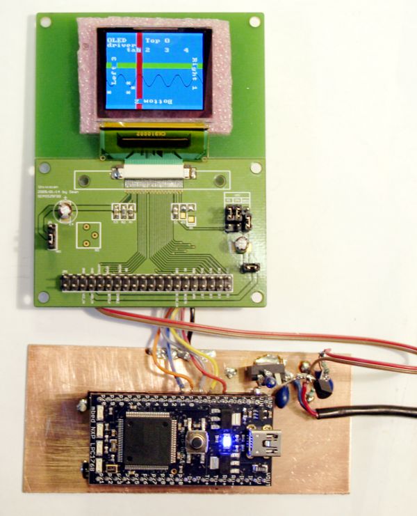
Photo
Here is a picture of the evaluation board being driven by the MBED. It's not the neatest prototype in the world since I've soldered directly to the pins of the Densitron evaluation board. The MBED, however, is in a DIL socket because I'd like to keep it clean and re-use it ;-) I drive the demo with a single 13V regulated D.C. supply which is then further regulated for the 3V3 required by the Densitron board and 5V for supplying the MBED via the VIN pin.
As is usual trying to photograph displays, it looks more washed-out than it actually is due to the amount of ambient light required to work with a camera that I can't use properly yet ;-) The colours, especially the blue are much deeper than the photo suggests. Another issue is that the display does flicker at 70Hz. This is fine for looking at but it took several attempts to get a photo without strobing artefacts.
References
Syncoam SEPS525F data sheet (link to Farnell website)
Evaluation board data sheet (link to Farnell website)
2 comments
You need to log in to post a comment
OLED
OLED Driver for the Densitron DD-160128FC-1A using the Syncoam SEPS525F driver chip
Page owner: Simon Blandford
Created 12 Jan 2010.
Last updated 12 Jan 2010
Hello here is an EAGLE library for XF2M35151A socket which is used on that connection board.
It's with description on each pin :)