Adafruit TCS34725 RGB Color Sensor
Color Sensor
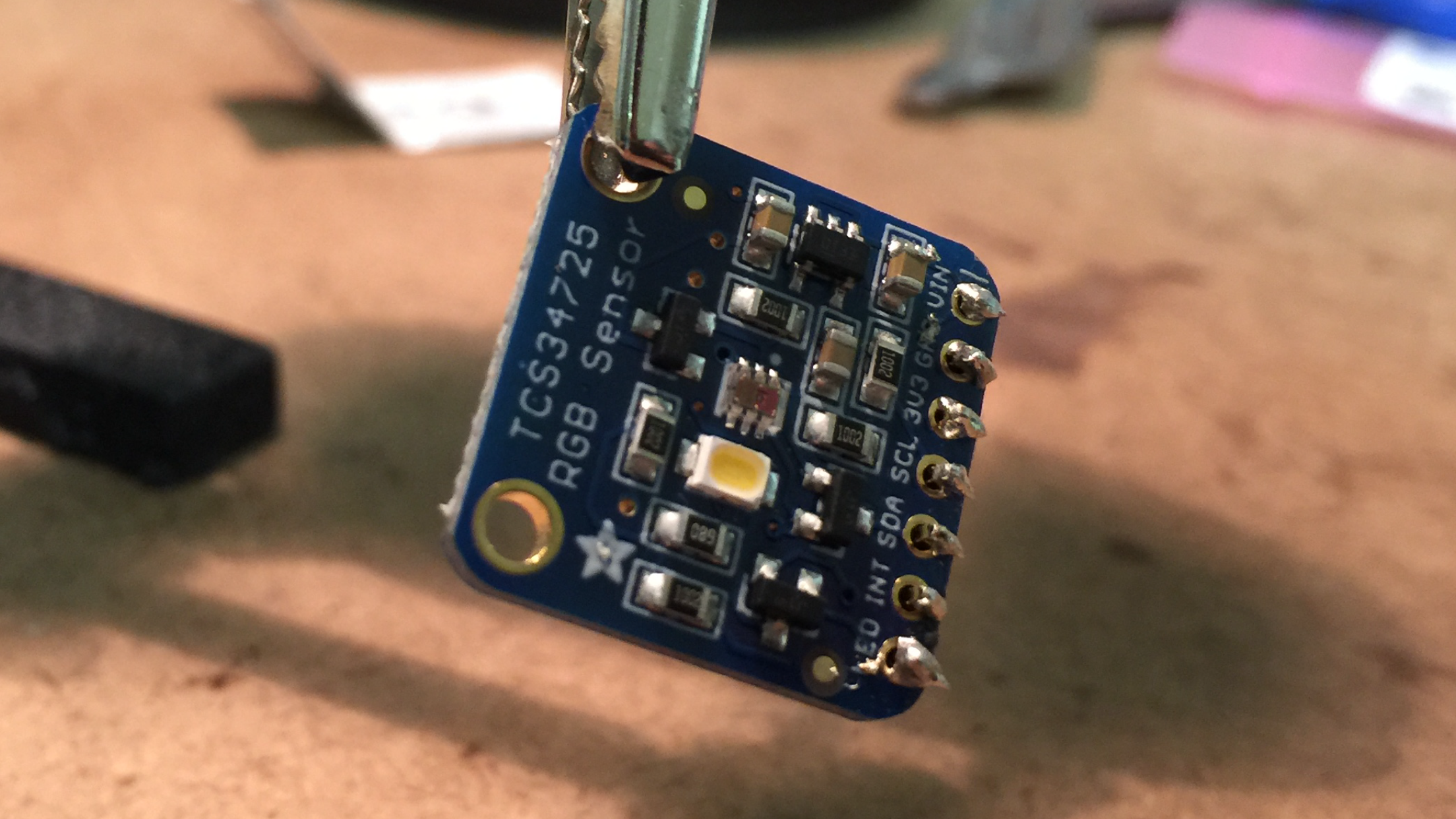
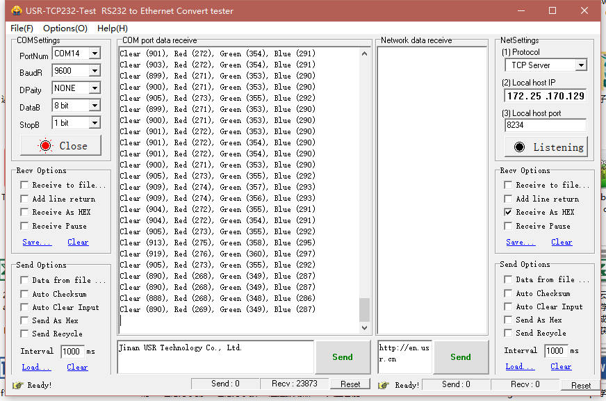
This guide is for setting up the Adafruit TCS34725 I2C Color Sensor to obtain 16-bit values for red, green, and blue wavelengths of light. The sensor communicates on the SDA and SCL pins and requires 3.3v to operate its logic. There is a white LED on the chip to assist the color sensor in reading the color of the object. The LED can be operated with any DigitalOut pin on the MBED. The 16-bit values for each of the three wavelength readings are simply relative intensities that can be analyzed using use-specific logic to determine the human-associated color.

Color Sensor Hookup
| MBED | TCS34725 |
|---|---|
| gnd | gnd |
| Vout | Vin |
| p9 | SDA |
| p10 | SCL |
| p11 | LED |
Introductory Code
The below code has been taken from MBED user: HannesTschofenig. The code has been modified specifically for the MBED LPC1768.
 #include "mbed.h"

I2C i2c(p9, p10); //pins for I2C communication (SDA, SCL)
Serial pc(USBTX, USBRX);    //Used to view the colors that are read in

int sensor_addr = 41 << 1;

DigitalOut green(LED1);
DigitalOut led(p11);

int main() {
    pc.baud(9600);
    green = 1; // off

    // Connect to the Color sensor and verify

    i2c.frequency(200000);

    char id_regval[1] = {146};
    char data[1] = {0};
    i2c.write(sensor_addr,id_regval,1, true);
    i2c.read(sensor_addr,data,1,false);

    if (data[0]==68) {
        green = 0;
        wait (2);
        green = 1;
        } else {
        green = 1;
    }

    // Initialize color sensor

    char timing_register[2] = {129,0};
    i2c.write(sensor_addr,timing_register,2,false);

    char control_register[2] = {143,0};
    i2c.write(sensor_addr,control_register,2,false);

    char enable_register[2] = {128,3};
    i2c.write(sensor_addr,enable_register,2,false);

    // Read data from color sensor (Clear/Red/Green/Blue)
    led = 1;
    while (true) {
        char clear_reg[1] = {148};
        char clear_data[2] = {0,0};
        i2c.write(sensor_addr,clear_reg,1, true);
        i2c.read(sensor_addr,clear_data,2, false);

        int clear_value = ((int)clear_data[1] << 8) | clear_data[0];

        char red_reg[1] = {150};
        char red_data[2] = {0,0};
        i2c.write(sensor_addr,red_reg,1, true);
        i2c.read(sensor_addr,red_data,2, false);

        int red_value = ((int)red_data[1] << 8) | red_data[0];

        char green_reg[1] = {152};
        char green_data[2] = {0,0};
        i2c.write(sensor_addr,green_reg,1, true);
        i2c.read(sensor_addr,green_data,2, false);

        int green_value = ((int)green_data[1] << 8) | green_data[0];

        char blue_reg[1] = {154};
        char blue_data[2] = {0,0};
        i2c.write(sensor_addr,blue_reg,1, true);
        i2c.read(sensor_addr,blue_data,2, false);

        int blue_value = ((int)blue_data[1] << 8) | blue_data[0];

        // print sensor readings

        pc.printf("Clear (%d), Red (%d), Green (%d), Blue (%d)\n", clear_value, red_value, green_value, blue_value);
        //The above code displays the red, green, and blue values read in by the color sensor.
        wait(0.5);
    }

}
4 comments on Adafruit TCS34725 RGB Color Sensor:
Please log in to post comments.


I do not know how to connect this color sensor and nucleo. Is electrolytic capacitor etc installed on the way?