Important changes to repositories hosted on mbed.com
Mbed hosted mercurial repositories are deprecated and are due to be permanently deleted in July 2026.
To keep a copy of this software download the repository Zip archive or clone locally using Mercurial.
It is also possible to export all your personal repositories from the account settings page.
What is "PCA9629" ?
Information
The stepper motor controller PCA9629A is available now!
This "A-version (PCA9629A)" is a feature extended version on "non-A (PCA9629)".
If you are thinking new design, the PCA9629A can be a good option.
The PCA9629A has several new features like on-the-fly speed change, extended ramp controls, filter settings for GPIO port inputs, braking and releasing by timeout.. and more.
Please find detail information here.
The "A-version" chip is pin-compatible to "non-A". So it can be replaced easily.
The register mapping and bit fields are re-defined. Those should be cared by software.
A sample code and a class library are available for mbed.
Import programPCA9629A_Hello
Hello program for PCA9629A. Demonstrates basic operations of PCA9629A component library.
Import libraryPCA9629A
PCA9629A component library
A Stepper motor controller
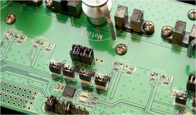
PCA9629 (x5) demo board: PCA9629, 4x FETs and stepper motor
The PCA9629 is an I2C-bus controlled low-power CMOS device that provides all the logic and control required to drive a four phase stepper motor. PCA9629 is intended to be used with external high current drivers to drive the motor coils. The PCA9629 supports three stepper motor drive formats: one-phase (wave drive), two-phase, and half-step. In addition, when used as inputs, four General Purpose Input/Outputs (GPIOs) allow sensing of logic level output from optical interrupter modules and generate active LOW interrupt signal on the INT pin of PCA9629. This is a useful feature in sensing home position of motor shaft or reference for step pulses. Upon interrupt, the PCA9629 can be programmed to automatically stop the motor or reverse the direction of rotation of motor.
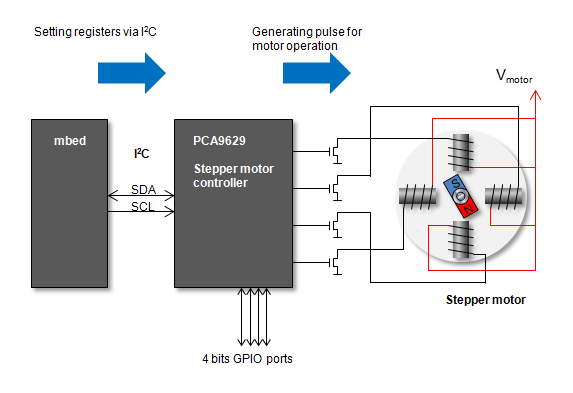
Communicate with mbed through I2C. The motor can be operated by register settings
Output wave train is programmable using control registers. The control registers are programmed via the I2C-bus. Features built into the PCA9629 provide highly flexible control of stepper motor, off-load bus master/micro and significantly reduce I2C-bus traffic. These include control of step size, number of steps per single command, number of full rotations and direction of rotation. A ramp-up on start and/or ramp-down on stop is also provided.
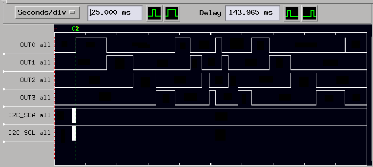
Waveforms: Lower 2 lines are I2C bus. Upper 4 lines are output for motor driver stage
Motor moving 16 steps with acceleration and deceleration after register setting via I2C
The PCA9629 is available in a 16-pin TSSOP package and is specified over the -40 deg-C to +85 deg-C industrial temperature range.
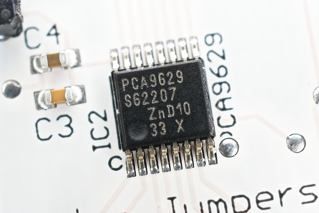
TSSOP16 package
Datasheet is available at next URL.
http://www.nxp.com/documents/data_sheet/PCA9629.pdf
Hardware
A sample schematic diagram is shown in next picture.
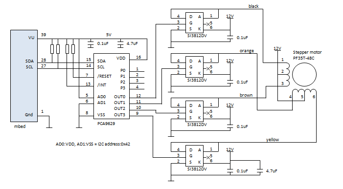
This schematic diagram shows a sample of the PF35T-48C stepper motor. It is using 12V supply voltage for motor and driving by SI3812DV FETs.
Pull-up resisters: For /RESET and /INT pins : 4.7K-ohms, for I2C signals (SDA and SCL) : >1.3k-ohms.
NOTE
For the correct operation of the "auto interrupt" demo, the GPIO port P0(pin1) and P1(pin2) must be connected to sensor input. signal edge of those pins are treated as the interrupt.
Sample code
This sample code operates the PCA9629 using its class library.
For the details of the library, please find information in library page.
Import libraryPCA9629
PCA9629 a stepper motor controller class library
API details are available in here
This program targets PCA9629 which has I2C address of 0x42 on I2C bus on pin28 and pin27 of mbed. 4 types motor actions are demonstrated in sequence (following 1..4 steps in loop).
- Simple motor turn demo
- Motor moved 96 steps with 100pps (pulse persecond) speed
- Then the motor turn reversed, move 48 steps by 50pps.
- Ramp control demo
- total operation time = 2 seconds, initial speed = 40.69pps, rotations = 5turns+0steps, ramp-up enable = enable, ramp-down enable = enable, rotate direction = CW
- The ramp control can be done with several register settings. The setting value calculation can be done by register setting tool (an Excel worksheet) from NXP.
- Auto interrupt demo
- The GPIO inputs can be used as interrupt for PCA9629. The operation can be stopped or change the direction of turn.
- This is turn direction auto reversing demo. Motor will switch the direction 12 steps after interrupt signal assertion.
- The register setting of interrupt operation can be done by register setting tool also.
- This demo works correctly only when sensor signals available on P0(pin1) and P1(pin2) input pins.
- Speed change demo
- Changing motor speed in 5 steps from 55pps to 275pps.

 PCA9629 Stepper motor controller