Seeed TFT Shield + FRDM-KL25Z
Step 1: Arduinoifying your FRDM board
The first step to interfacing any Arduino shield with the FRDM-KL25Z is soldering female header strips to the outer row of holes. Depending on the kind of header strips you have, breaking them apart may prove to be a bit messy. Don't forget your safety glasses!
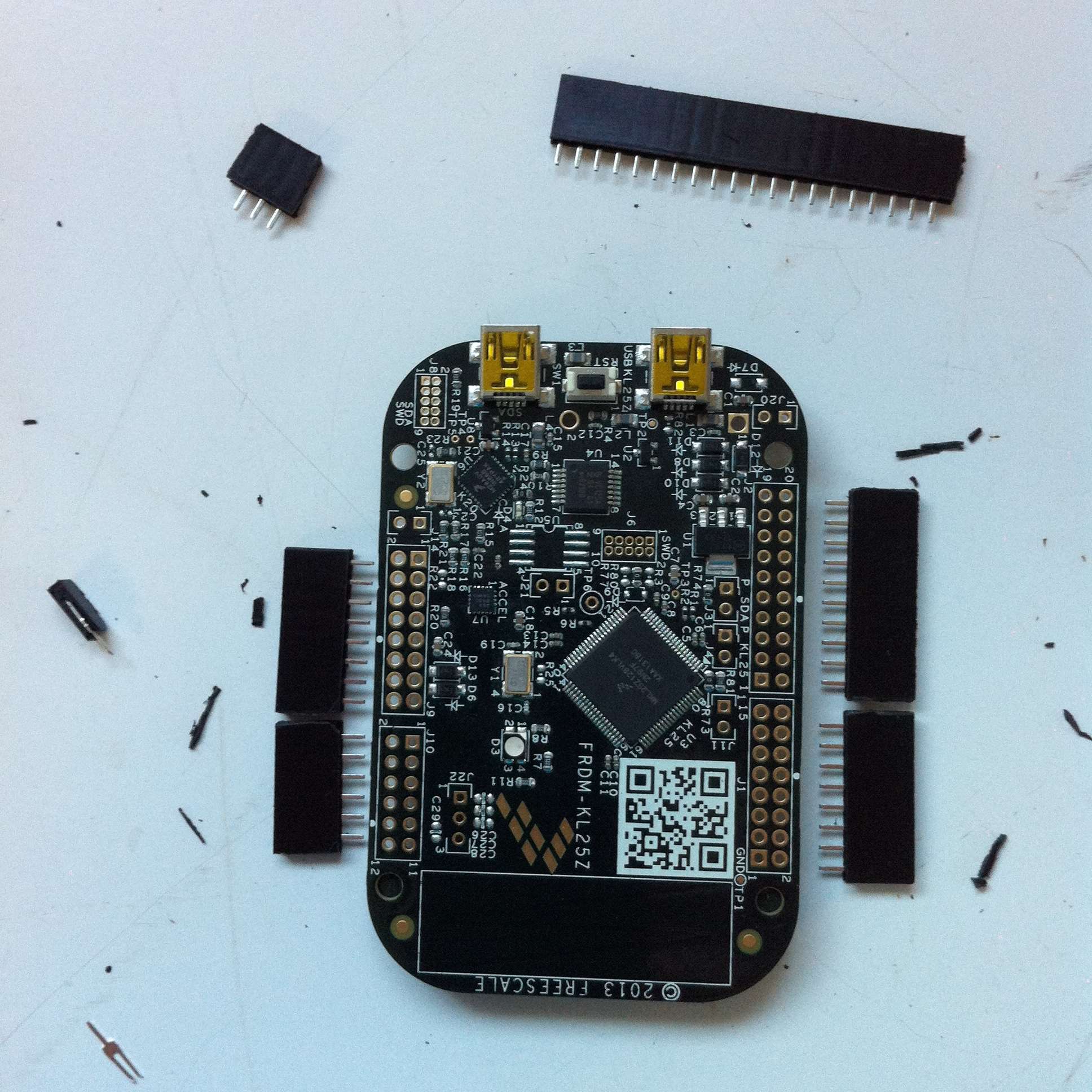
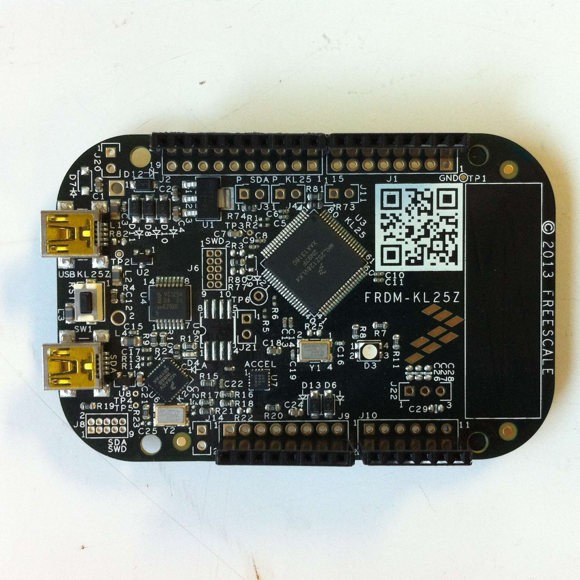
Step 2: Configuring your TFT Shield
Some of the control signals for the TFT Shield are not connected to the Arduino headers by default. Instead, they connect to a small 2x3 header, which isn't present on the FRDM-KL25Z. Fortunately for us, there are 3 solder jumpers, P1, P2, and P3, that will connect the signals when bridged. Simply heat them up with a soldering iron and bridge them together.
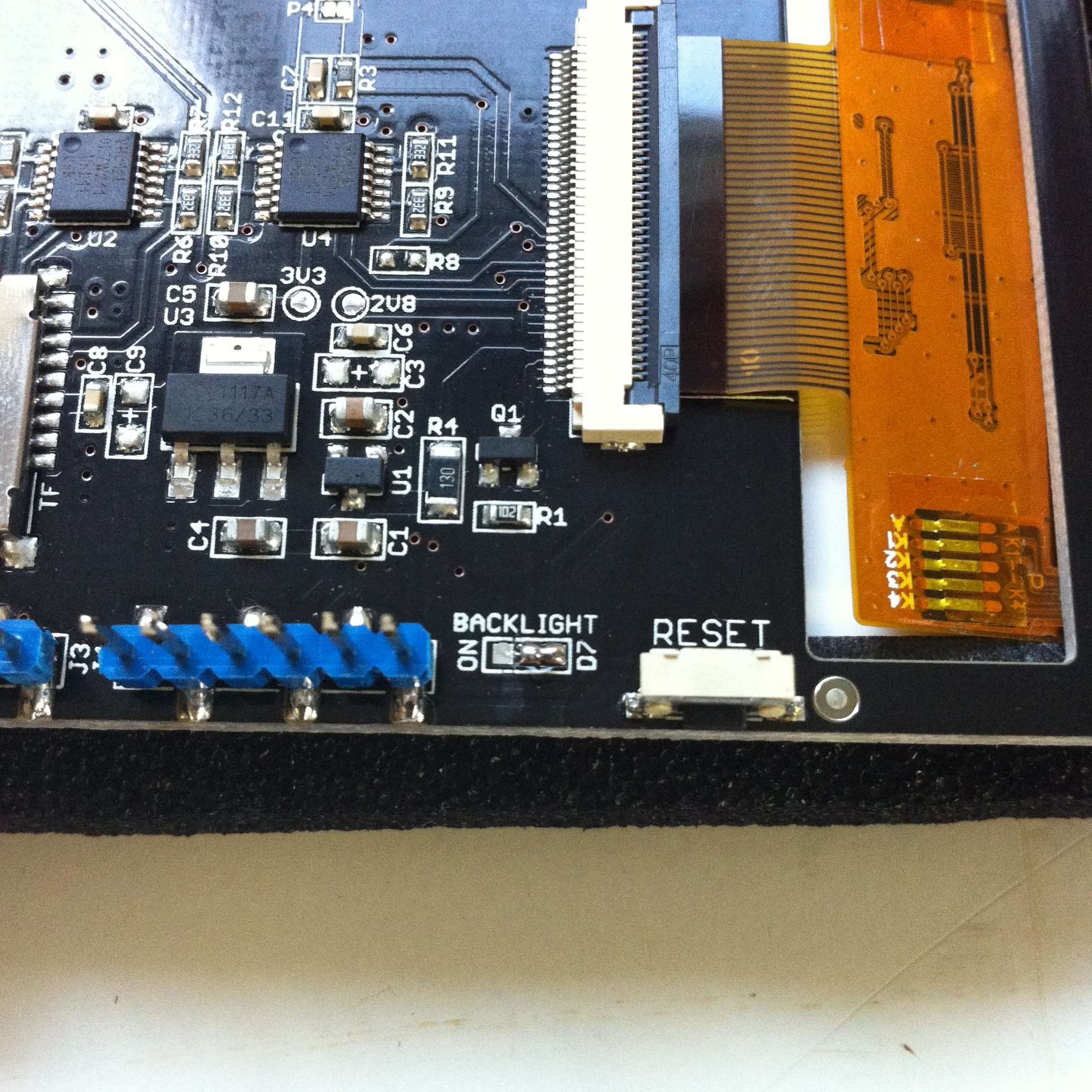
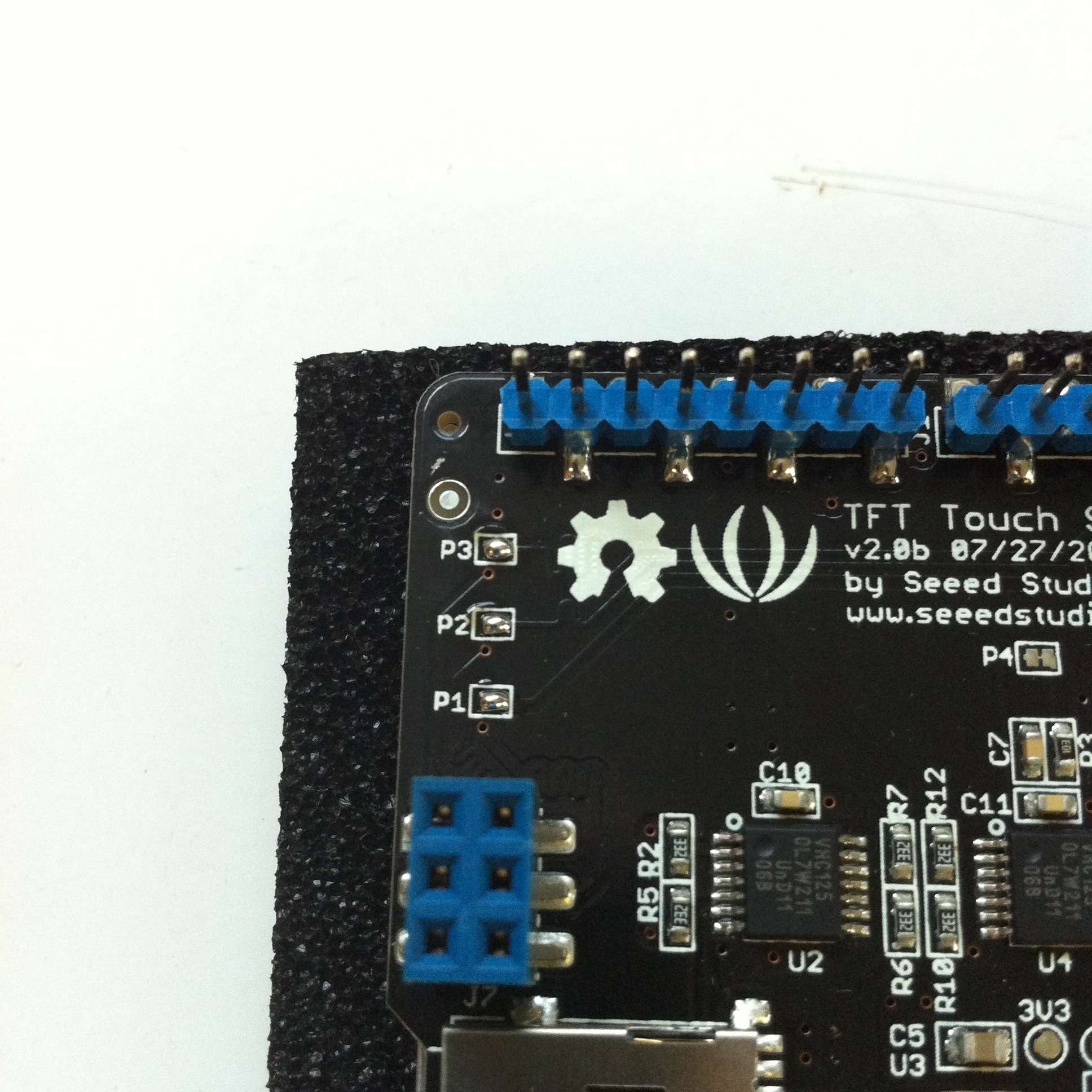 While we're at it, lets change the BACKLIGHT jumper from ON to D7. This will allow us to control the backlight in software.
Step 3: Success!
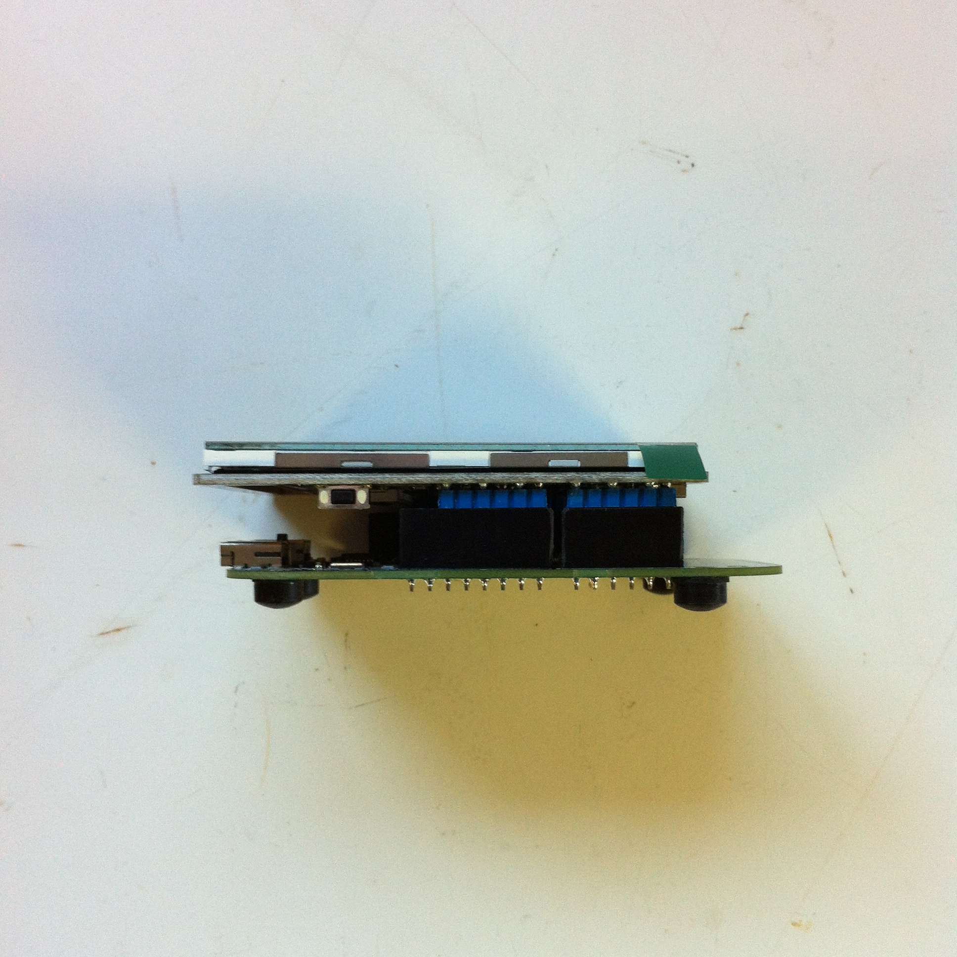
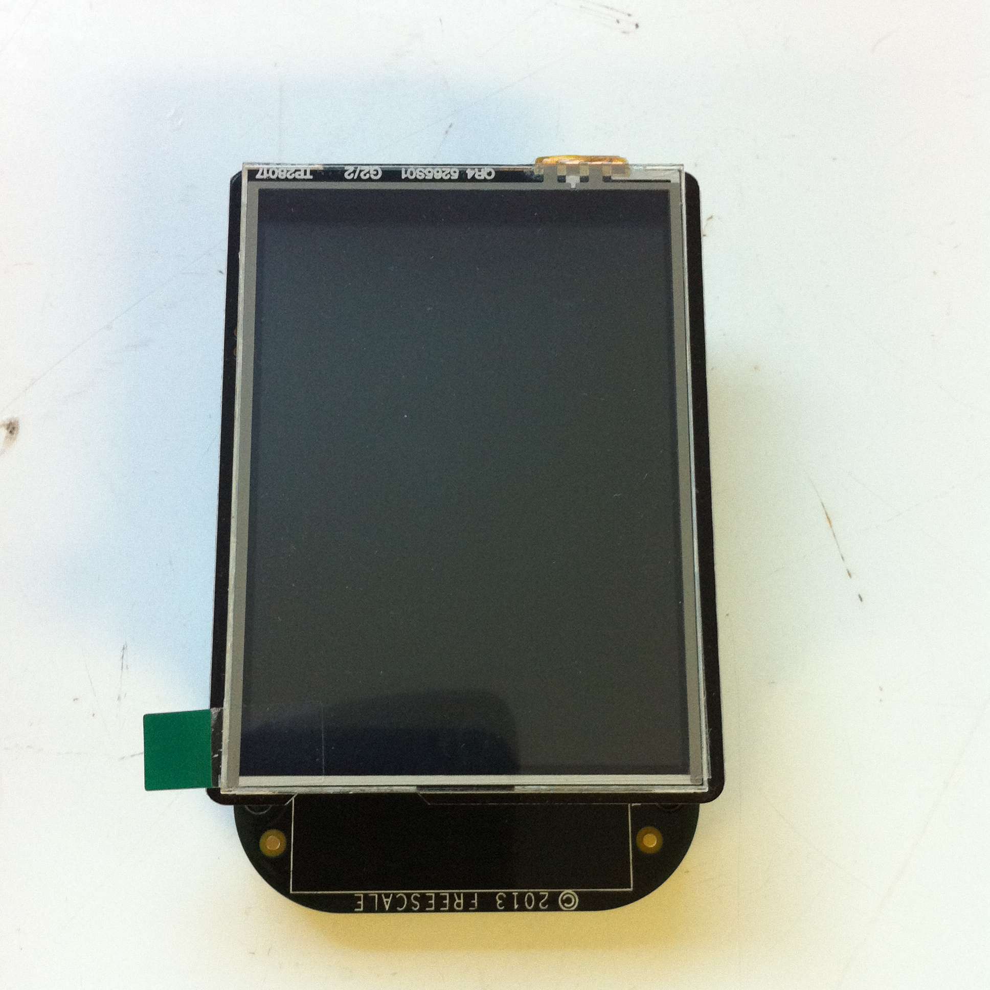
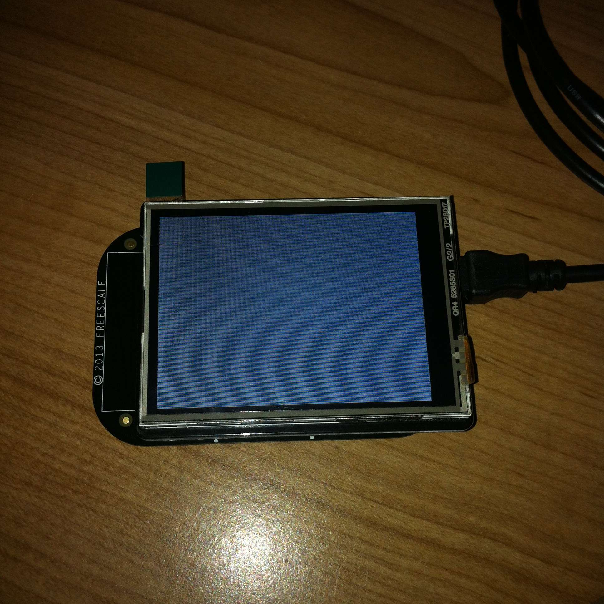
That's it, snap the two boards together and you're good to go!
Please log in to post comments.
